
Electronic Module Wedge Package Socket Locking Force Measurement System

An electronic module and measurement system technology, applied in the direction of force/torque/work measuring instruments, measuring devices, instruments, etc., can solve the problems of inaccurate measurement, high thermal conductivity locking strip 4 without accurate parameters, and inflexible locking force measurement distance Adjustment and other issues

Active Publication Date: 2021-11-19
10TH RES INST OF CETC
View PDF7 Cites 0 Cited by
  • Summary
  • Abstract
  • Description
  • Claims
  • Application Information

AI Technical Summary

Problems solved by technology

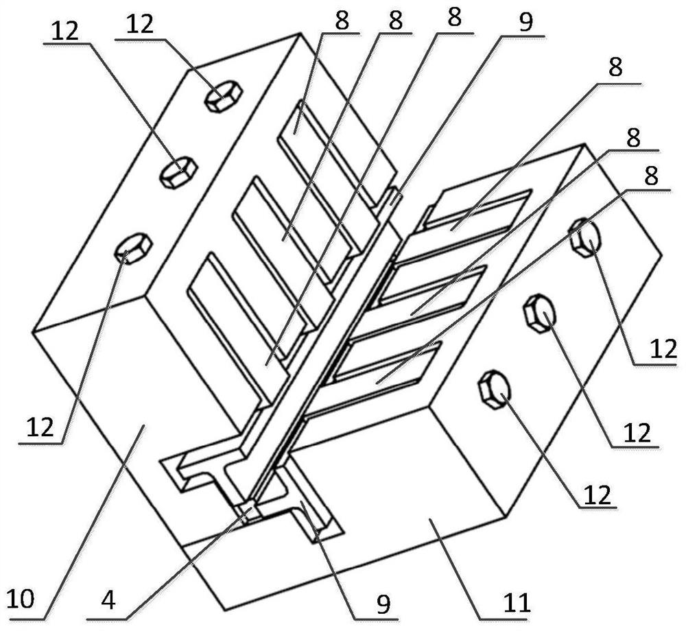
Traditional locking force measurement systems can only test single-degree-of-freedom locking devices, especially for Figure 5 In the high thermal conductivity locking strip 4, the stroke on the two degrees of freedom is related to the locking force. If a single degree of freedom locking force test system is used, it cannot be measured accurately, which leads to the high thermal conductivity locking strip 4 There are no accurate parameters in the application process, the screw rotation torque cannot be provided during the design process, and the pressure between the locking bar and the module cannot be estimated at the same time
[0004] The published "A Measuring Device for Clamping Force of Clamping in Stamping Dies of Large and Small Sizes" in the prior art can only measure the locking force of a single degree of freedom; the measuring distance of the locking force cannot be flexibly adjusted; most of the locking force measurements are The description of the measuring device does not form a real-time locking force measurement system, and it is impossible to realize the real-time change measurement of the locking force under vibration and overload conditions, the change of the locking force loading process, etc.

Method used


Image

  • Electronic Module Wedge Package Socket Locking Force Measurement System
  • Electronic Module Wedge Package Socket Locking Force Measurement System
  • Electronic Module Wedge Package Socket Locking Force Measurement System

Examples


Embodiment Construction

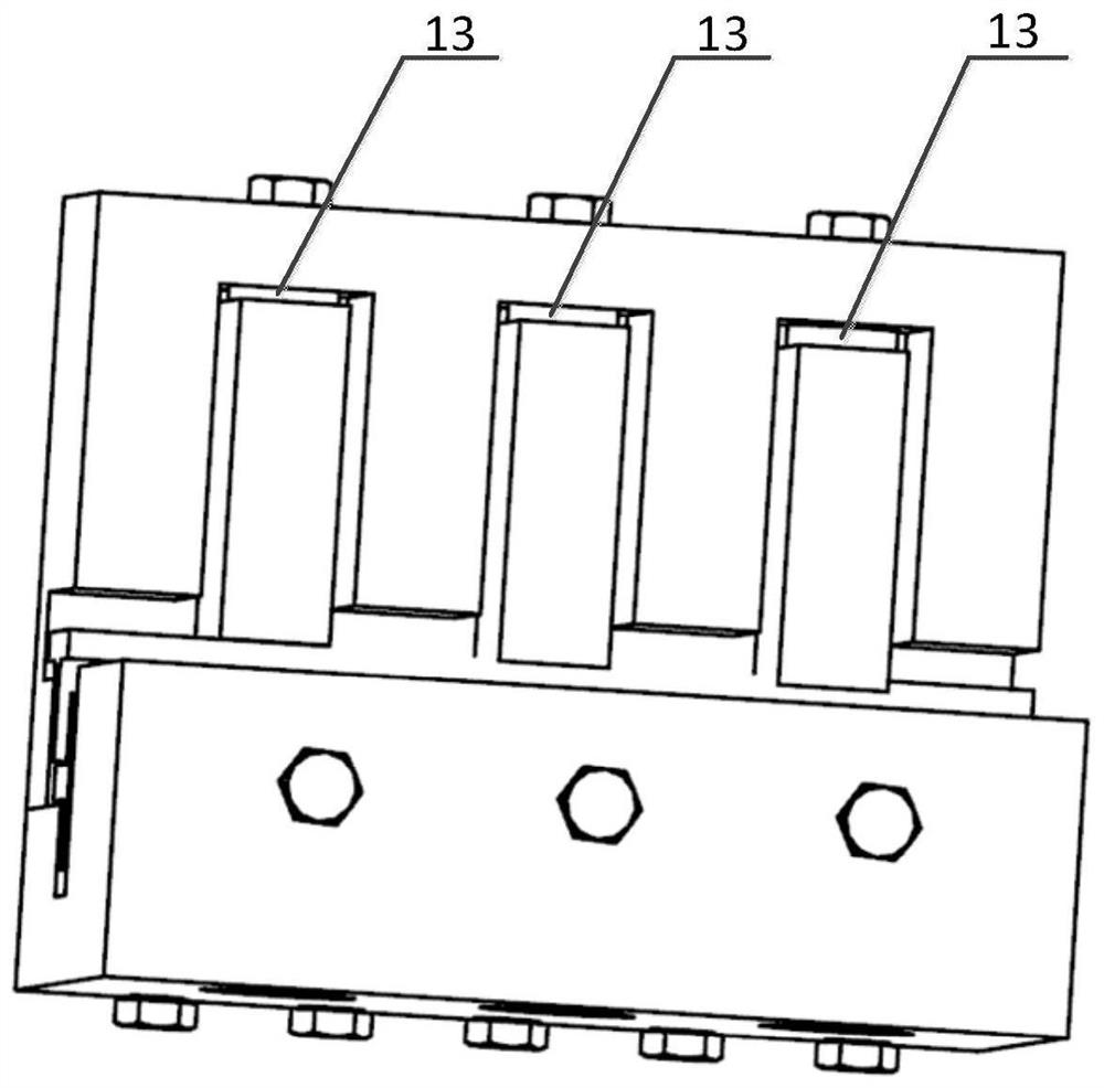
[0019] refer to Figure 1-Figure 4 . In the preferred embodiment described below, a kind of electronic module wedge packaging socket locking force measurement system includes: installed on the vibration table, impact table, connected between the host computer 5 and the test module through the data connection line 6 Data acquisition instrument 7. Among them, the test module has a rectangular short base 10 and a long base 11 which are vertically overlapped with each other, and the formed L-shaped root is formed with a low thermal conductivity locking strip 2 and a high thermal conductivity locking strip perpendicular to each other. 4, the end face of the L-shaped vertical body is also provided with positioning bolts 12 arranged in a line array and a line array groove for assembling the pressure sensor 8 on the inner side of the vertical plane, and the data connection line 6 of each pressure sensor 8 passes through the line array The wire hole at the back end of the groove is c...


PUM


Abstract

The invention discloses a measuring system for the locking force of a wedge-shaped packaging slot of an electronic module, which aims to provide a measuring system capable of measuring the locking force of a two-degree-of-freedom wedge-shaped locking bar. The present invention is realized through the following technical scheme: adopt the test module of the short base and the long base of the rectangular body which are vertically overlapped with each other, set the positioning bolts arranged in a line array and the interlocking bolts on the end surface of the formed L-shaped vertical body Assemble the linear array groove of the pressure sensor on the inner side of the vertical surface. Each pressure sensor is connected to the data acquisition instrument through the wire hole at the back end of the linear array groove. The positioning bolt is combined with the pressure sensor and inserted into the low thermal conductivity locking strip, under the high thermal conductivity locking strip The stopper adjusts the test distance; the test module uploads the measurement results to the host computer in real time through the pressure sensor, dynamically tests the locking force of the wedge-shaped locking bar, and transmits and displays the measurement results in real time.

Description

technical field [0001] The invention relates to a locking force measurement system of a wedge-shaped locking bar fixing device for an electronic module chassis slot. In particular, it is a system for measuring the locking force of the locking strips in the form of wedge packaging of aviation high-density electronic modules. Background technique [0002] With the rapid development of computer technology, the design of various hardware of the computer itself is becoming more and more sophisticated. Among them, the development of integrated circuits has made the analog circuits and discrete components with single functions and large volumes in the past replaced by highly integrated, small and bulky components. Many functions are replaced by the modular structure of resource sharing, which popularizes the concept of computer replaceable modules. With the development of electronic technology, electronic equipment has developed from discrete to integrated, and independent electro...

Claims


Application Information

Patent Timeline
Patent Type & Authority Patents(China)
IPC IPC(8): G01L5/00
CPCG01L5/0038
Inventor 赵亮李俞先胡家渝翁夏何智航
Owner 10TH RES INST OF CETC
Learn More