
Safety protection device for high-current negative hydrogen ion source

A safety protection device, the technology of negative hydrogen ions, applied in the direction of discharge tubes, electrical components, circuits, etc., can solve problems such as damage to power supply, damage, gas breakdown, etc.

Pending Publication Date: 2020-06-26
CHINA INSTITUTE OF ATOMIC ENERGY
View PDF0 Cites 1 Cited by
  • Summary
  • Abstract
  • Description
  • Claims
  • Application Information

AI Technical Summary

Problems solved by technology

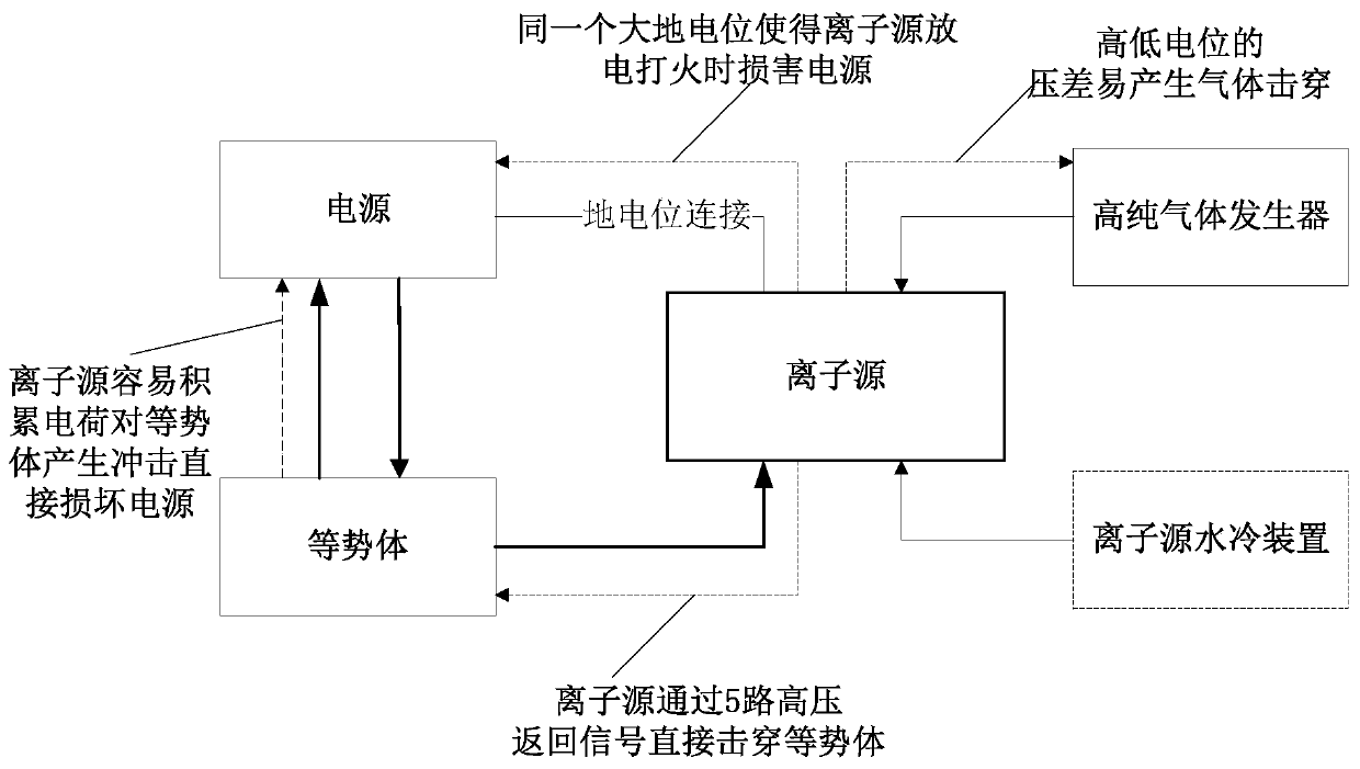
[0005] In order to solve the problems existing in the prior art, the present invention proposes a safety protection device for a strong-current negative hydrogen ion source, the purpose of which is to solve the problem that the high and low potential difference between the ion source and the high-purity gas generator is prone to gas breakdown Problem; Solve the problem that the ion source and the power supply have the same earth potential, when the ion source accumulates charge and discharges and damages the power supply; solve the problem that the ion source and the equipotential body have the same high potential, when the ion source accumulates charge, discharges and fires and damages the equipotential body The problem; when a high voltage is applied to the ion source, the high voltage of the ion source conducts electricity and thus breaks down the problem of the low voltage power supply

Method used


Image

  • Safety protection device for high-current negative hydrogen ion source
  • Safety protection device for high-current negative hydrogen ion source
  • Safety protection device for high-current negative hydrogen ion source

Examples


Embodiment 1

[0058] Embodiment 1: Installation method of power supply and equipotential body in the cabinet

[0059] For the installation position of the power supply and equipotential body in the cabinet, refer to Figure 5 , the 5 power supplies are on the top, and the equipotential body is on the bottom. The cabinet adopts a 19-inch 42U standard chassis, and the height of the chassis is an integer multiple of U. The rear panel of the cabinet is designed as a hinged side door. Consider the heat dissipation design between the power supplies of the cabinet and the top cover of the cabinet. The power supply from bottom to top is high voltage power supply, plasma power supply, suction electrode power supply, arc voltage power supply, and filament power supply. The five power supplies are arranged in a reasonable space according to the needs. Among them, the high-voltage power supply is connected to the 220V AC power supply, and the plasma power supply, the suction electrode power supply,...


PUM


Abstract

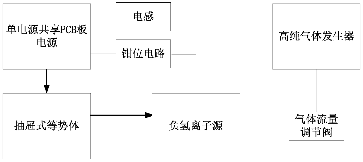
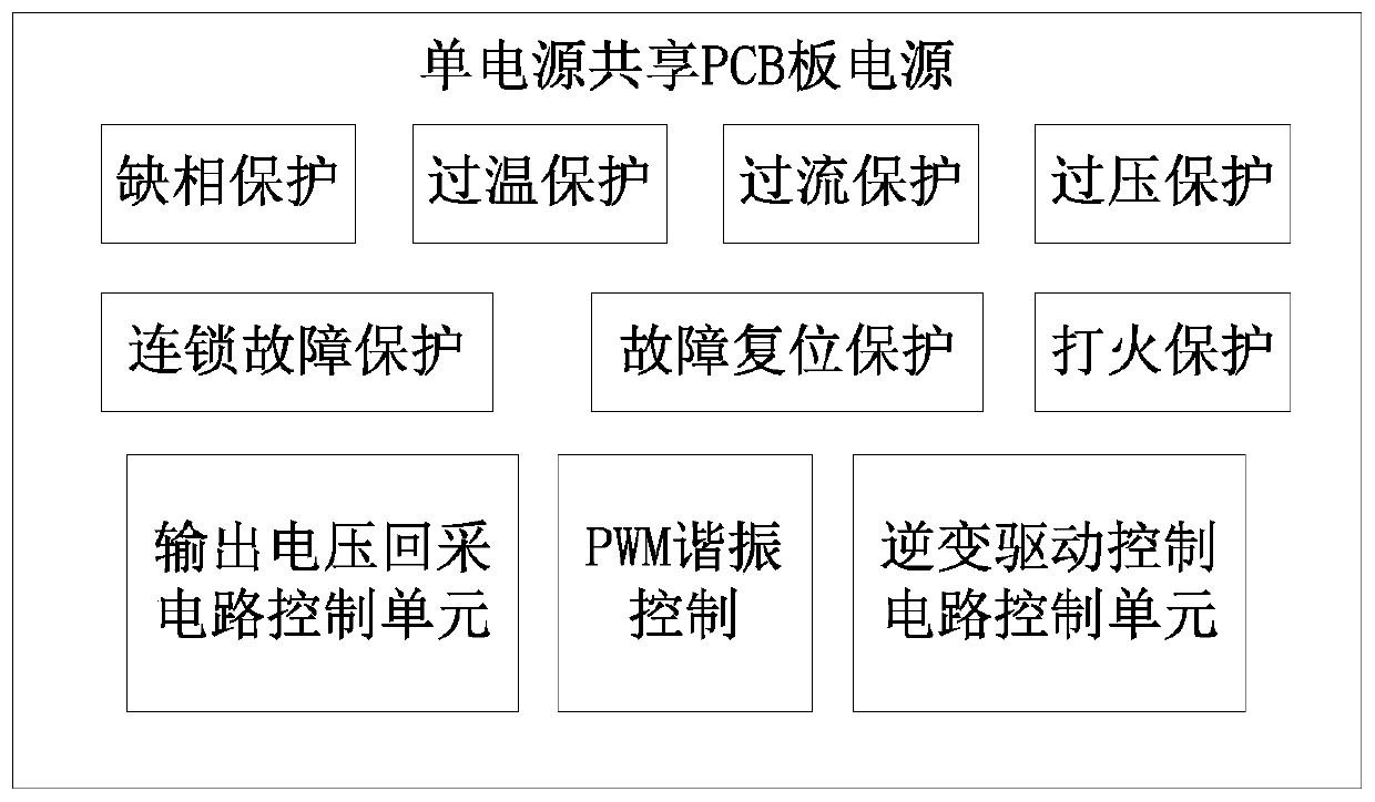
The invention discloses a safety protection device for a high-current negative hydrogen ion source. The device comprises an ion source which is used for generating negative hydrogen ions, a high-purity gas generator which is used for supplying gas to the negative hydrogen ion source, and a power supply which is used for supplying power to the negative hydrogen ion source; a high-voltage equipotential body is further arranged between the power supply and the negative hydrogen ion source, and the power supply supplies power to the negative hydrogen ion source through the high-voltage equipotential body; a load discharge prevention device is also arranged between the power supply and the negative hydrogen ion source; a high-potential gas flow regulating valve is also arranged between the high-purity gas generator and the negative hydrogen ion source; the power supply is a single-power-supply shared PCB power supply; the high-voltage equipotential body is a drawer type equipotential body;the ground potential of the power supply end and the ground potential of the negative hydrogen ion source end are the same ground potential, and the high potential of the high-voltage equipotential body end and the high potential of the negative hydrogen ion source end are the same high potential of -30 KV or above. All the parts are organically combined, all the parts support and depend on one another after combination, and the overall safety protection problem of the high-current negative hydrogen ion source is solved.

Description

technical field [0001] The invention relates to the field of accelerators, in particular to a safety protection device for a strong current negative hydrogen ion source Background technique [0002] The beam source of any accelerator needs to be provided by the ion source, so the quality and stability of the beam generated by the ion source directly affect the working efficiency of the accelerator. The working principle of the filament-driven multi-peak magnetic field ion source is: by heating the filament, the filament material emits an electron and collides with hydrogen molecules in the multi-peak magnetic field. Constrained by the multi-peak magnetic field, the hydrogen molecules undergo a complex dissociation and recombination process to form a plasma. After filtering the fast electrons by the tangential magnetic field, the ratio of the required negative hydrogen ions is increased, and then the electrons are filtered by the deflection magnetic field, and finally the bea...

Claims


Application Information

Patent Timeline
IPC IPC(8): H01J37/24
CPCH01J37/241
Inventor 王景峰贾先禄张贺李鹏展侯世刚
Owner CHINA INSTITUTE OF ATOMIC ENERGY
Learn More