
A power supply control method and power supply circuit based on flyback converter

A technology of flyback converter and power supply control, which is applied in the direction of control/regulation system, DC power input conversion to DC power output, instruments, etc. It can solve the problems of affecting system efficiency, high heat generation, and low LDO efficiency

Active Publication Date: 2021-04-23
SOUTHCHIP SEMICON TECH SHANGHAI CO LTD
View PDF6 Cites 0 Cited by
  • Summary
  • Abstract
  • Description
  • Claims
  • Application Information

AI Technical Summary

Problems solved by technology

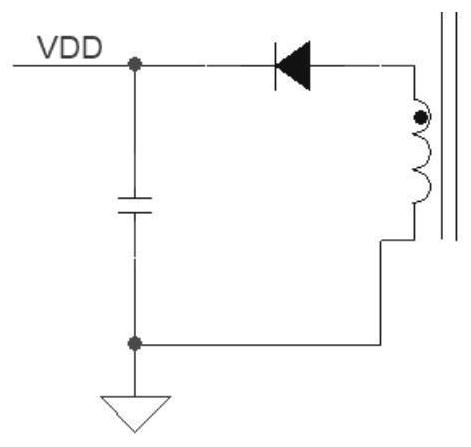
When Vout changes from 3V to 21V, it means that the range of VDD also changes greatly. The minimum operating voltage of VDD is 10V, which means that VDD is 10V when the output is 3V, and it will be as high as 70V when the output is 21V. This will bring about two problems: first, high voltage means high requirements for the withstand voltage of the VDD pin, and high requirements for process withstand voltage; secondly, when the internal supply current of VDD remains unchanged, high voltage means high Loss Ploss=VI, the heat caused by high loss is also a big problem
Therefore, the first power supply method is not suitable for applications with a wide output voltage range.
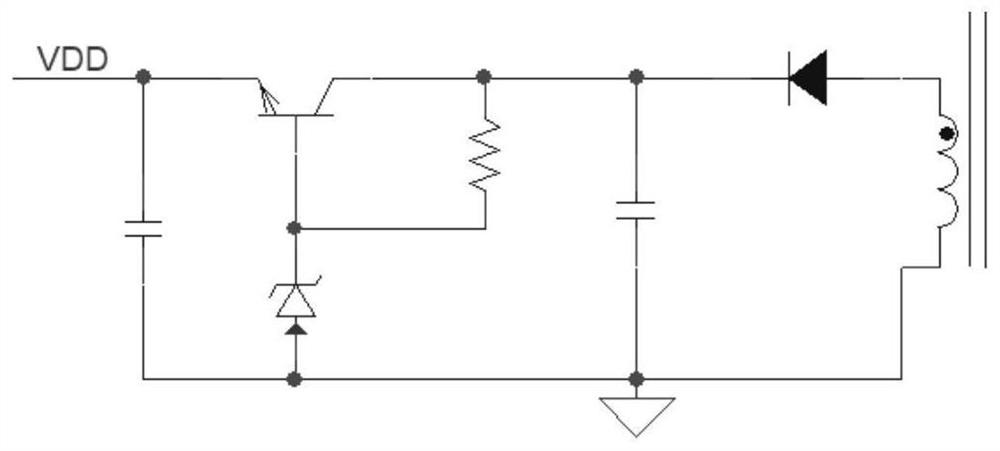
[0005] The second is LDO (low dropout linear regulator) power supply, such as figure 2 As shown, but because the efficiency of LDO is generally low, although this solution can be applied to occasions with a wide output voltage range, it will affect the efficiency of the entire system
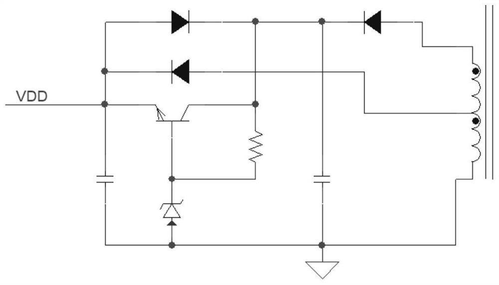
[0006] The third is to improve the LDO power supply, such as image 3 As shown, this solution not only solves the efficiency problem, but also can be applied to applications with a wide output voltage range, but because of the addition of a set of transformer auxiliary windings and two diodes, the cost is relatively high

Method used


Image

  • A power supply control method and power supply circuit based on flyback converter
  • A power supply control method and power supply circuit based on flyback converter
  • A power supply control method and power supply circuit based on flyback converter

Examples


Embodiment Construction

[0052] The present invention will be further described below in conjunction with the accompanying drawings and specific embodiments.

[0053] The present invention proposes a power supply control method based on a flyback converter, which improves the auxiliary winding unit in the traditional flyback converter, such as Figure 4 , 5 As shown, in the power supply control method proposed by the present invention, the auxiliary winding unit of the flyback converter includes an auxiliary winding, a diode D3, a first capacitor C8, a second capacitor C6 and an inductor L2. One end of the auxiliary winding is grounded, and the other end is connected to a diode The anode of D3; one end of the inductor L2 is connected to the cathode of the diode D3 and grounded after passing through the second capacitor C6, and the other end is used as the control terminal SW; the lower plate of the first capacitor C8 is grounded, and the upper plate is connected to the flyback through the starting cir...


PUM


Abstract

A power supply control method and power supply circuit based on a flyback converter. In the start-up phase, the input voltage of the flyback converter charges the capacitor through the start-up circuit, so that the power supply voltage of the flyback converter rises to the working voltage, and then The flyback converter starts to work, and the output power supply voltage is the power supply for the external circuit; the power supply voltage of the flyback converter is monitored in real time, and when the power supply voltage is lower than the turn-on control voltage, the power supply voltage is boosted and controlled; when the power supply voltage is higher than When the control voltage is turned off, the step-up control of the supply voltage is stopped. The present invention makes the power supply voltage of the flyback converter meet the power supply requirements by raising the auxiliary winding voltage, reduces the high voltage requirement for the auxiliary winding voltage, and is suitable for applications where the output voltage range of the flyback converter is wide; in addition The invention also has the characteristics of high power supply efficiency, low loss, low cost and easy integration into chips.

Description

technical field [0001] The invention belongs to the technical field of switching power supplies, and relates to a power supply control method based on a flyback converter and a power supply circuit based on a flyback converter for realizing the power supply control method. Background technique [0002] Flyback converter, also known as single-ended flyback or "Buck-Boost" converter, gets its name because the output terminal obtains energy when the primary winding is disconnected from the power supply. The flyback converter is widely used in low-power power supplies and various power adapters because of its simple circuit structure and low cost. [0003] In the start-up phase of the flyback converter, the power is generally taken from the bus voltage VBUS through the start-up resistor or JFET (junction field effect transistor), and the bus voltage is the input voltage of the flyback converter; For power supply, three power supply methods based on the flyback converter in the ...

Claims


Application Information

Patent Timeline
Patent Type & Authority Patents(China)
IPC IPC(8): H02M3/335
CPCH02M3/33507H02M1/0048Y02B70/10
Inventor 高建龙杨坤
Owner SOUTHCHIP SEMICON TECH SHANGHAI CO LTD
Learn More