Stirring and gluing device with simple structure for double-component quick-drying glue

A simple structure, two-component technology, applied to mixers with rotating stirring devices, devices for coating liquid on the surface, dissolving, etc., can solve the problems of wasting rubber materials, affecting the use of glue, and high cost, and achieve extended use Long life, good mixing effect and wide glue path

Active Publication Date: 2020-06-30
重庆津竹缘创新科技有限公司
View PDF12 Cites 2 Cited by
  • Summary
  • Abstract
  • Description
  • Claims
  • Application Information

AI Technical Summary

Problems solved by technology

However, due to the dense helical channel for cutting and mixing glue in the static mixing tube, the lumen is narrow, tortuous, and the surface area is large. For intermittent glue, especially quick-drying glue, it is very easy to cause the enrichment of cured products, which affects Glue flow rate and mixing effect will eventually cause blockage, and frequent replacement of static mixing tubes not only affects work efficiency, wastes rubber, and the cost of tube replacement is unbearable, but also affects environmental protection
The conventional dynamic agitator uses a motor to drive the paddle to mix the rubber in a finger-sized mixing dish. For the same reason, the paddle and the mixing dish will continue to adhere and deposit with the increase in use time and frequency, and some will start to solidify. The residual glue then causes clogging
In addition, the existence of the agitator in the mixing container affects the use of glue, and the conventional lifting agitator has a complicated structure and high cost
These problems have seriously affected the assembly line operation of the factory and affected the popularization and application of new environmentally friendly and quick-drying AB glue.

Method used


Image

  • Stirring and gluing device with simple structure for double-component quick-drying glue
  • Stirring and gluing device with simple structure for double-component quick-drying glue
  • Stirring and gluing device with simple structure for double-component quick-drying glue

Examples


Embodiment 1

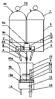
[0067] like figure 1 As shown, the storage barrel 2 containing components A and B is provided with a barometer 1a and a pipeline 1b communicating with the air compressor air storage tank on the barrel cover 1 to maintain a constant pressure so that the glue flow and glue output are stable. , the discharge pipes on the two storage buckets 2 are respectively connected with the inlet ends of the double-pipe feed valve 4, and the outlet end 6a of the double-pipe feed valve 4 passes through the plate surface 5 supported by the support frame 16 and is respectively connected with the two pipes. The conduit 6 is plugged. A micro-motor 3 is arranged between the two conduits 6, which is fixed on the plate surface 5 by the iron sheet 3a and the holding iron 3b, and the rotating shaft 7 at the lower end of the motor 3 is connected to the stirring rod 9 through an adjustable coupling 8, The lower end of the stirring rod has a hinged blade 9a with a smaller rotation radius at a higher posi...

Embodiment 2

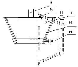
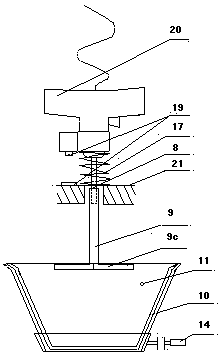
[0069] like figure 2 As shown in the figure, the two-component rubber material that flows out of the self-pressure AB storage tank according to a certain proportion and quantitatively flows through the respective pipelines through the double-pipe feed valve fixed on the operating platform at a lower position, and the double-pipe feed The outlet end of the valve is sleeved with a conduit, and the distance between the two outlets of the conduit is such that it can completely flow into the wide-mouth rubber nozzle. A motor is fixed directly above the wide-mouth rubber nozzle 10 through a support frame, and there is a rotating shaft with a taper at the lower end. The wide-mouth rubber nozzle 10 with the side wall whose mouth diameter is larger than the height and has an inclination of 25~45 degrees can also use its taper to stack several identical wide-mouth rubber nozzles in order to replace the innermost layer if necessary. A shaft pin 11 is set near the opposite side and the ...

Embodiment 3

[0071] The wide-mouth rubber nozzle 10 in the present invention can also be connected with the rotating shaft 11 or other turning mechanisms through the extension structure, so that the wide-mouth rubber nozzle 10 can be easily installed and disassembled; the shaft pin 11 can also be directly or indirectly fixed with the wide-mouth rubber nozzle. Thus, the reversal is realized by controlling the rotation of the rotating shaft 11; the sliding block 13 can also be detachably connected with the wide mouth rubber nozzle 10, and the control part 14 of the sliding block 13 is connected with the inversion mechanism.


PUM


Abstract

The invention relates to a device for metering, mixing, stirring and discharging the double-component quick-drying glue, in particular to a stirring and gluing device with a simple structure for double-component quick-drying glue. The stirring and gluing device comprises storage barrels containing a component A and a component B separately, a pipeline for allowing each single component to flow toa mixer, and a mixer. The stirring and gluing device is characterized in that a plurality of wide-mouth glue nozzles are arranged in a rotating body with a horizontal rotating shaft in order to form acirculating wide-mouth glue nozzle combination; a pump body or a valve body to which the two-component glue flows in proportion and a stirrer are arranged above the wide-mouth glue nozzle in place, and the stirrer can be separated from the wide-mouth glue nozzle; and after the circulating wide-mouth glue nozzle combination rotates by 90 degrees towards a center shaft in the horizontal direction,the first wide-mouth glue nozzle completes gluing, the second wide-mouth rubber nozzle moves in place, and the operation cycles in order. The use time of the stirring mixer can be greatly prolonged, the structure is simple, and the use is convenient.

Description

technical field [0001] The invention relates to a device for uniformly stirring and mixing according to a certain proportion for a two-component adhesive, which is especially suitable for the filling or dispensing of quick-drying adhesive with good fluidity. Background technique [0002] The existing two-component glue application equipment includes pneumatic or electric spraying machine, glue spraying machine, glue filling machine, glue dispensing machine, glue gun, etc. Generally, the volume ratio or mass ratio is adjusted by gear pump, air pump or electronic balance. The components of the glue are mixed through a static mixing tube or a dynamic stirrer and then flow out from the glue outlet, which is suitable for two-component adhesives with slow reaction and better fluidity. However, because the static mixing tube is provided with dense spiral channels for cutting and mixing glue, the tube cavity is narrow, coiled, and the surface area is large. The flow rate and mixing...

Claims


Application Information

Patent Timeline
Patent Type & Authority Applications(China)
IPC IPC(8): B05C5/00B05C11/10B01F7/16B01F13/08B01F13/10
CPCB05C11/1036B05C11/10
Inventor 卢清友卢思竹袁小亚李巧红邱顺
Owner 重庆津竹缘创新科技有限公司
Why Eureka
Try Eureka