
Liquid nitrogen nail gun device

A nail gun and liquid nitrogen technology, applied in nailing tools, U-shaped nail tools, manufacturing tools, etc., can solve the problems of high power consumption, unsafe nail guns, etc., achieve simple structure and eliminate potential safety hazards , Solve the effect of large power consumption

Active Publication Date: 2020-06-30
TIANJIN UNIV
View PDF10 Cites 0 Cited by
  • Summary
  • Abstract
  • Description
  • Claims
  • Application Information

AI Technical Summary

Problems solved by technology

[0003] The technical problem to be solved by the present invention is to provide a new type of nail gun scheme and device that relies on liquid nitrogen gasification to generate power for the defects and insufficiencies of existing nail guns. The realization of this nail gun will solve the problem of traditional nail guns. Unsafe problems caused by heat during use; liquid nitrogen green cleaning avoids harmful substances that may be produced after traditional gas combustion and gunpowder bullet gasification; the start-up of the liquid nitrogen nailing device involved requires a small amount of electricity, Solve the problem of large power consumption of traditional electric nail guns

Method used


Image

  • Liquid nitrogen nail gun device
  • Liquid nitrogen nail gun device
  • Liquid nitrogen nail gun device

Examples


Embodiment 1

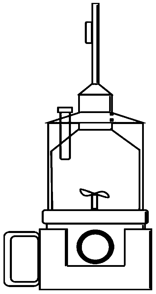
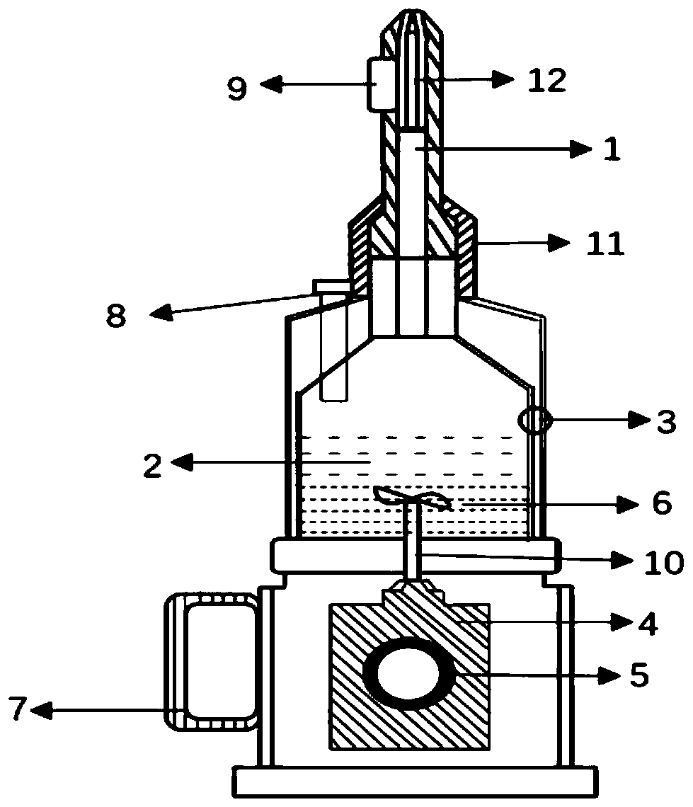
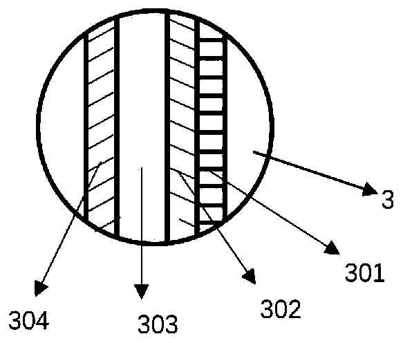
[0030] Please refer to figure 1 , figure 2 , image 3 , Figure 4 and Figure 5 , Embodiment 1 of the present invention provides a liquid nitrogen nail gun. The gun body itself includes a barrel 1, a gasification chamber 2, a gasification chamber wall 3, a motor 4, a motor switch 5, a fan blade 6, a handle 7, a liquid inlet Port 8 and magnet 9, metal bearing 10, axle sleeve 11 and nail 12. The gun barrel 1 is arranged above the gasification chamber 2, and the lower end of the gun barrel 1 is connected to the upper port of the gasification chamber 2 through a shaft sleeve 11. The matching stepped card slot has an internal thread structure at the other end, through which the internal thread mechanism is connected with the external thread on the upper port of the gasification chamber. The entire barrel structure is simple and easy to disassemble. The nail 12 is placed in the gun barrel, and the nail is absorbed by the magnet 9 installed on one side of the gun barrel to prev...


PUM


Abstract

The invention relates to a liquid nitrogen nail gun device which comprises a gun barrel, a gasification chamber, a motor and a handle. The gun barrel is located at the uppermost part of a nail gun, and the lower portion of the gun barrel is connected with an upper end opening of the gasification chamber. The upper end opening of the gasification chamber is of a necking-down structure. A liquid inlet is formed in one side of the top of the gasification chamber. The gasification chamber is of a double-layer structure, and a vacuum interlayer is arranged between the inner wall and the outer wallof the gasification chamber. Fan blades are arranged in the gasification chamber, the fan blades are connected with a motor through a connecting metal bearing, and the motor is connected with the handle. The gasification chamber is a power generation cavity needed by nail shooting and is used for storing liquid nitrogen and water, and the liquid nitrogen is finally gasified to generate pressure. The fan blades are started through the motor to fast rotate, due to the fan blades which rotate rapidly in the gasification chamber, the liquid nitrogen and water can be rapidly mixed, the gasificationrate of the liquid nitrogen is rapidly increased when the liquid nitrogen meets water, generated high pressure provides power, and then the nails can be shot up rapidly. By means of the liquid nitrogen nail gun device, the problem that when a traditional nail gun is used, heat emitting happens, and safety cannot be ensured is solved; and the device overall has the beneficial effects that the structure is simple, potential safety hazards are eliminated, and environment friendliness is achieved.

Description

technical field [0001] The technical solution of the present invention relates to a liquid nitrogen nail gun device, specifically a kinetic energy generating device that generates instantaneous high pressure through rapid gasification of liquid nitrogen to generate kinetic energy. Background technique [0002] A nail gun, a tool used to drive nails into wood, walls, etc., has in many ways replaced the hammer as the builder's tool of choice. Existing nail guns can be mainly divided into pneumatic nail guns, powder-driven nail guns, combustion-powered nail guns, electric nail guns, and electromagnetic-driven nail guns according to the source of power. These nail guns usually use compressed air (pneumatic), electromagnetic drive, highly flammable gas or gunpowder to gasify in the cavity, thereby forming power, and the nail is shot out by the nail gun needle. The problem that present nail gun exists is: the first, for the nail gun of electric and combustion power, especially be...

Claims


Application Information

Patent Timeline
IPC IPC(8): B25C1/04B25C7/00
CPCB25C1/04B25C7/00
Inventor 王立英孙长龙胡玉高曹荠蓬沙健华
Owner TIANJIN UNIV
Learn More