Operation method of multistage oil-water separation tank of intelligent pulse electrostatic coalescence electrode

An oil-water separation tank and electrostatic coalescence technology, applied in the direction of electric/magnetic refining, etc., can solve the problems of increased operation and maintenance costs, poor properties, and increased floor space, so as to reduce sewage treatment costs and environmental protection pressure, Reduce the number of equipment stages and equipment, and reduce the effect of operation and maintenance costs

Pending Publication Date: 2020-06-30
LUOYANG ZHENGYUAN PETROCHEM
View PDF0 Cites 4 Cited by
  • Summary
  • Abstract
  • Description
  • Claims
  • Application Information

AI Technical Summary

Problems solved by technology

[0002] In recent years, as most oilfields in my country have entered the late stage of exploitation, on the one hand, the water content of the produced fluid has increased, and the water content of the produced fluid in some offshore oilfields can reach more than 99%. The produced fluid in many oilfields is seriously emulsified, which brings many problems to the conventional oil-water separator: 1. Due to the high water content, poor properties and serious emulsification of the produced fluid, the water content may be high after passing through the conventional oil-water separator, and entering the electric dehydration equipment will cause An increase in current, or even tripping, will affect the safe and stable operation of the electric dehydration equipment, and

Method used


Image

  • Operation method of multistage oil-water separation tank of intelligent pulse electrostatic coalescence electrode
  • Operation method of multistage oil-water separation tank of intelligent pulse electrostatic coalescence electrode
  • Operation method of multistage oil-water separation tank of intelligent pulse electrostatic coalescence electrode

Examples


Embodiment 1

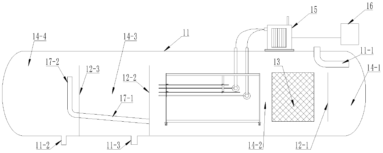
[0036] A transformer 15 is installed on the upper side of the tank body 11, and there is a wire between the transformer 15 and the controller 16. The steady flow orifice plate 12-1, the oil weir plate 12-2, and the water weir plate 12 are arranged in the tank body 11 from right to left. -3, there is a gap between the steady flow orifice 12-1 and the top and bottom of the tank body 11, and there is a gap between the oil weir plate 12-2 and the water weir plate 12-3 and the top of the tank body 11, A steady flow chamber 14-1 is formed between the steady flow orifice 12-1 and the right end of the tank body 11, the top of the tank body 11 corresponds to the steady flow chamber 14-1, and a crude oil inlet pipe 11-1 is arranged, and the steady flow orifice 12-1 and the oil An oil-water separation chamber 14-2 is formed between the weir plates 12-2, an oil chamber 14-3 is formed between the oil weir plate 12-2 and the water weir plate 12-3, and an oil discharge pipe is provided at the...

Embodiment 2

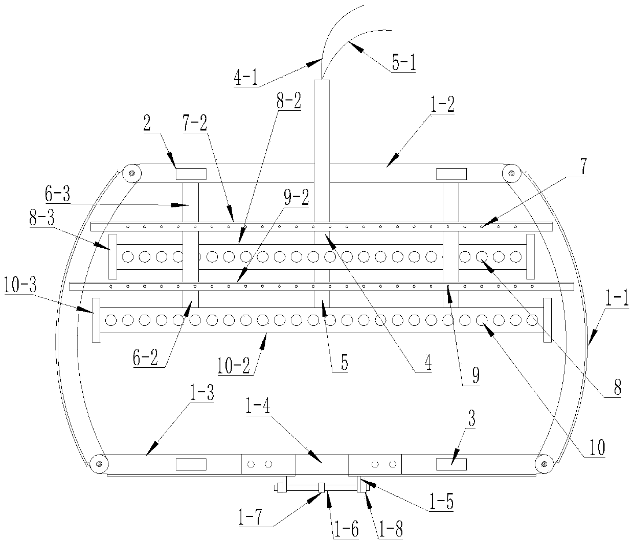
[0048] The structure of the jacking mechanism is as follows: a lifting lug 1-5 is set below the end of the lower horizontal plate 1-3 near the gap, a screw 1-6 is set between the threaded holes of a pair of lifting lugs 1-5, and the screw 1-6 Adjusting nut 1-7 is set in the middle of -6, and the two sides of adjusting nut 1-7 on screw 1-6 are set with external threads in opposite directions, and the two ends of screw 1-6 correspond to the threaded holes of a pair of lifting lugs 1-5 For screw connection, lock nuts 1-8 are arranged at both ends of the screw rod 1-6 through a pair of lifting lugs 1-5.

Embodiment 3

[0050] A protective fixing sleeve 1-4 is arranged between the opposite ends of the pair of lower horizontal plates 1-3 through screws, the lower end of the protective fixing sleeve 1-4 is open, and the section of the protective fixing sleeve 1-4 is C-shaped. The C-shaped opening faces downward.

[0051] The AC 380v50Hz power supply of the network first passes through the circuit breaker and the thyristor rectifier MTC. The functions include rectification and voltage regulation, and then enters the frequency conversion converter in the pulse transformer. The electric field in the desalination tank, there is a detection circuit in the transformer, which continuously monitors the secondary voltage and electric field voltage output by the pulse transformer, and the output secondary current and electric field current, and the detected signal is sent to the microcomputer controller CPU and EM In the module, on the one hand, after being processed, it is sent to the operator in the ce...


PUM


Abstract

The invention discloses an operation method of a multistage oil-water separation tank of an intelligent pulse electrostatic coalescence electrode. The amount of high-water-content crude oil in an oil-water separation chamber is continuously increased, so that the liquid level continuously rises; the liquid level of the high-water-content crude oil sequentially enters a first-stage electrostatic coalescence oil-water separation area, a second-stage electrostatic coalescence oil-water separation area, a third-stage electrostatic coalescence oil-water separation area, a fourth-stage electrostaticcoalescence oil-water separation area and a fifth-stage electrostatic coalescence oil-water separation area upwards; the purpose of controlling the electric quantity of an electrostatic field in eacharea is achieved by adjusting the electric quantity on the first insulating electrode and the second insulating electrode through a controller, after water-containing crude oil enters the electrostatic field, water drops in the water-containing crude oil are polarized and deformed under the action of electrostatic field force, small water drops are coalesced into large water drops to settle downwards, and it is guaranteed that the water content of the separated crude oil is greatly reduced; the problems of low dehydration rate and high oil content in drained water of a secondary separator aresolved by adding the electrostatic fields, the dehydration efficiency is effectively improved, and the production cost is reduced.

Description

technical field [0001] The invention relates to the technical field of crude oil-water separation, in particular to a method for operating a multi-stage oil-water separation tank of an intelligent pulse electrostatic coalescence electrode. Background technique [0002] In recent years, as most oilfields in my country have entered the late stage of exploitation, on the one hand, the water content of the produced fluid has increased, and the water content of the produced fluid in some offshore oilfields can reach more than 99%. The produced fluid in many oilfields is seriously emulsified, which brings many problems to the conventional oil-water separator: 1. Due to the high water content, poor properties and serious emulsification of the produced fluid, the water content may be high after passing through the conventional oil-water separator, and entering the electric dehydration equipment will cause An increase in current, or even a trip, will affect the safe and stable operatio...

Claims


Application Information

Patent Timeline
IPC IPC(8): C10G32/02
CPCC10G32/02
Inventor 张志平戴国华
Owner LUOYANG ZHENGYUAN PETROCHEM
Why Eureka
Try Eureka