
Deep water surface casing running tool relief simulating experimental device and method

A technology for simulating an experimental device and a feeding tool, which is applied in the field of a deep water surface catheter feeding tool release simulation experimental device, can solve problems such as inability to be accurately and effectively released, and achieve the effect of improving safety

Active Publication Date: 2020-06-30
CHINA NAT OFFSHORE OIL CORP +1
View PDF7 Cites 2 Cited by
  • Summary
  • Abstract
  • Description
  • Claims
  • Application Information

AI Technical Summary

Problems solved by technology

[0006] The purpose of the present invention is to provide a deep-water surface conduit feeding tool release simulation device and method, which is used to solve the accidents that cannot be accurately and effectively released during the actual production process when the deep-water surface conduit feeding tool is not accurately and effectively released. question

Method used


Image

  • Deep water surface casing running tool relief simulating experimental device and method
  • Deep water surface casing running tool relief simulating experimental device and method

Examples


Embodiment 1

[0032] Embodiment 1 provides a deep-water surface conduit running tool release simulation experiment device, the structure of which will be described in detail below.

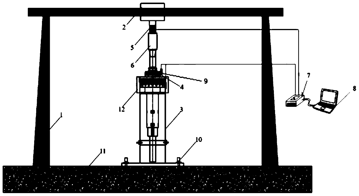
[0033] refer to figure 1 , the deep-water surface conduit feeding tool release simulation experiment device includes an experiment frame 1, a low-pressure wellhead head 3, a deep-water surface conduit feeding tool 4, a rotating motor 2, a lifting motor device, a coupling 6, a data collector 7 and a computer 8 .

[0034] The bottom of the test frame 1 is provided with a base 11, specifically, the base 11 is a reinforced concrete structure base. The low-pressure wellhead head 3 is fixed on the base 11 by fastening bolts 10 .

[0035] The upper part of the low-pressure wellhead head 3 is a deep-water low-pressure wellhead head, which is provided with two bosses, and the lower part of the deep-water surface conduit feeding tool 4 is provided with two flanges. The flanges at the bottom of the 4 are matched, and t...

Embodiment 2

[0063] Embodiment 2 provides a kind of deep-water surface layer conduit into tool release simulation experiment method, adopts the deep-water surface layer conduit into tool release simulation experiment device that embodiment 1 provides, and this release simulation experiment method comprises the following steps:

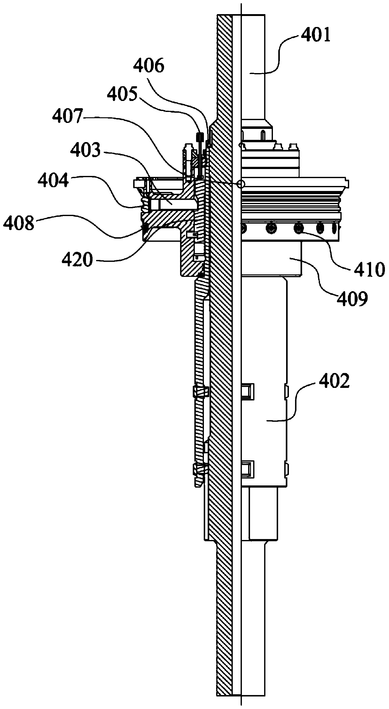
[0064] Step S1: Cut off the release pin 406, and separate the mandrel 401 and the bushing 402;

[0065] Step S11: Install the rotating motor 2 on the horizontal plate of the test frame 1, and connect the mandrel 401 of the deep-water surface conduit feeding tool 4 to the output shaft of the rotating motor 2 through the coupling 6;

[0066] Step S12: start the rotating motor 2, rotate the mandrel 401 clockwise until the release pin 406 is cut off, the mandrel 401 is separated from the bushing 402, and the mandrel 401 is rotated and moved down;

[0067] Step S2: Cut off the positioning pin 408 and the anti-rotation pin 407;

[0068] Step S21: Set the lifting motor d...


PUM


Abstract

The invention discloses a deep water surface casing running tool relief simulating experimental device and method. The deep water surface casing running tool relief simulating experimental device comprises an experimental frame, a low-pressure well head, a deep water surface casing running tool, a rotating motor, a lifting motor device, a coupler, a data collector and a computer. An output shaft of the rotating motor and an output shaft of the lifting motor device are provided with a torque sensor and a tension sensor correspondingly. Multiple anti-rotation pin sensing sheets are arranged in the deep water surface casing running tool. The torque sensor, the tension sensor and the multiple anti-rotation pin sensing sheets are connected with the computer through multiple data lines. By the adoption of the deep water surface casing running tool relief simulating experimental device and method, by means of experiment stress analysis of operations, such as locking, relief and recycling, conducted on the deep water surface casing running tool, basis is provided for making a plan to optimize pin arrangement, and then the safety, efficiency and accuracy of the deep water jet operation of the deep water surface casing running tool are improved.

Description

technical field [0001] The invention relates to the technical field of offshore oil and gas drilling, in particular to a simulation experiment device and method for releasing a deep-water surface conduit into a tool. Background technique [0002] Deepwater drilling generally refers to drilling with a depth of more than 900 meters in offshore operations. During the process of deepwater drilling in the ocean, due to the low strength of the shallow undiagenetic strata on the surface of deepwater drilling, it is prone to collapse. The deepwater surface conduit is installed during the entire deepwater oil well construction process. The first layer of casing, which provides structural support for all subsequent casings and wellhead equipment, is the "throat" of deepwater drilling. [0003] The deep water surface conduit jetting running technology is a key link in the construction of deep water drilling projects. This technology can realize continuous drilling through multiple step...

Claims


Application Information

Patent Timeline
Patent Type & Authority Applications(China)
IPC IPC(8): E21B7/20E21B23/00
CPCE21B7/20E21B23/00
Inventor 刘书杰吴怡杨进李舒展杨玉贵焦金刚耿亚楠杨馥榕王宁朱国倞
Owner CHINA NAT OFFSHORE OIL CORP
Learn More