Shield head structure for effectively controlling ground surface settlement

A technology of surface subsidence and shield head, which is applied in the field of shield head structure, can solve the problems of surface subsidence and low efficiency, and achieve the effects of improving soil strength, protecting the ecological environment, and reducing the amount of muck

Inactive Publication Date: 2020-06-30
XUZHOU UNIV OF TECH
View PDF0 Cites 3 Cited by
  • Summary
  • Abstract
  • Description
  • Claims
  • Application Information

AI Technical Summary

Problems solved by technology

However, due to the large disturbance of the soil around the segment during the excavation process, the cutter head of the ordinary shield machine will cause the ground surface to settle; the existing external shell grouting technology can improve the Tunnel support strength; however, it needs to be processed after the tunneling of the shield machine, resulting in low efficiency; at present, there is no shield head structure that can be grouted during the tunneling of the shield machine, so that the waterproof grout and the excavation process Part of the generated muck is mixed and extruded outside the shield shell to form a waterproof layer outside the segment, which can not only improve the waterproof ability of the tunnel support structure, but also reduce the amount of muck transported to the surface during the construction process, so The shield head structure is the research direction of this industry

Method used


Image

  • Shield head structure for effectively controlling ground surface settlement
  • Shield head structure for effectively controlling ground surface settlement

Examples


Embodiment Construction

[0016] The present invention will be further described below.

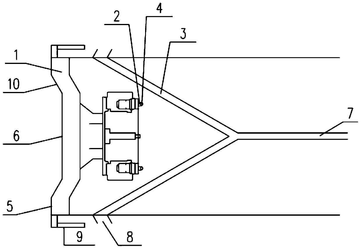
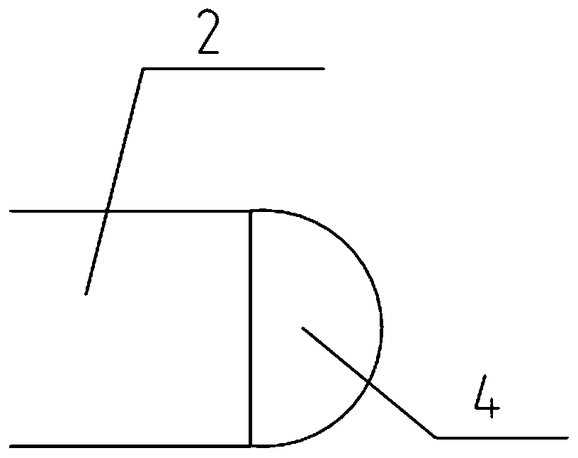
[0017] Such as figure 1 and figure 2 As shown, the present invention includes a cutter head overall 1, a shield shell I, a shield shell II, a grouting pipe 3 outside the shell, a pressure detection device and a conveying main pipe 7. The cutter head overall 1 is installed on the front end of the shield shell I, and the shield shell The rear end of I is coaxially fixedly connected with the front end of shield shell II;

[0018] Described cutter head overall 1 comprises primary excavation surface 5, cutting surface 10 and secondary excavation surface 6, and described primary excavation surface 5 and secondary excavation surface 6 are parallel to each other, primary excavation surface 5 and secondary excavation surface Excavation surface 6 is annular, and the annulus external diameter of secondary excavation surface 6 is less than the annulus internal diameter of excavation surface 5; The soil mouth 9 is outside ...


PUM

PropertyMeasurementUnit
Depthaaaaaaaaaa

Abstract

The invention discloses a shield head structure for effectively controlling the ground surface settlement. The shield head structure comprises a cutter head assembly, a shield shell I, a shield shellII, a shell outside injection pipe, a pressure detecting device and a conveying main pipe. The cutter head assembly is arranged at the front end of the shield shell I. The rear end of the shield shellI and the front end of the shield shell II are coaxially and fixedly connected. During tunneling, the ground stress in front of a shield head is detected in real time through the pressure detecting device, the thrust power of a shield tunneling machine is adjusted in real time according to a detection value, and the shield tunneling machine keeps at a stable thrust speed; in the tunneling process, waterproof slurry is discharged to the joint of the shield shell I and the shield shell II through an injection hole, at the moment, muck and the waterproof slurry make contact and are mixed to forma muck waterproof mixture, the muck waterproof mixture is extruded by the exterior of the shield shell II, and the muck waterproof mixture is compacted and fixed to a tunnel goaf surface formed aftertunneling of the shield tunneling machine; and thus, the soil body strength and waterproof treatment of the tunnel goaf surface are improved, the effect of preventing the ground surface settlement isrealized, a slope face is leveled, and the water seepage route is reduced.

Description

technical field [0001] The invention relates to a shield head structure, in particular to a shield head structure for effectively controlling ground surface subsidence. Background technique [0002] At present, by improving the utilization of underground space, ground traffic congestion and other situations can be effectively alleviated. In the process of constructing underground space, due to the constraints of urban environmental factors such as construction sites and road traffic, traditional construction methods are difficult to apply universally. Considering that tunnel construction with shield machine has the advantages of high degree of automation, saving manpower, fast construction speed, one-time hole formation, not affected by climate, control of ground subsidence during excavation, reduction of impact on ground buildings and underwater construction. It does not affect the water surface traffic and other characteristics when digging. Based on the above advantages...

Claims


Application Information

Patent Timeline
IPC IPC(8): E21D9/08E21D9/093E21D11/38E21D9/06G01L1/00
CPCE21D9/0607E21D9/08E21D11/38E21D9/093G01L1/00G01L1/02
Inventor 朱思宇于洋韩雨珩陈定超赵祥岍
Owner XUZHOU UNIV OF TECH
Why Eureka
Try Eureka