Rapid detection device for liquid crystal antenna panel

An antenna panel and detection device technology, which is used in measurement devices, optical performance testing, optical instrument testing, etc., can solve the problem of not being able to completely detect defective liquid crystal antenna panel products, and achieve increased types, detection efficiency, and accuracy. , the effect of reducing the missed detection rate

Pending Publication Date: 2020-06-30
BEIJING HUAMETA TECH CO LTD
View PDF0 Cites 2 Cited by
  • Summary
  • Abstract
  • Description
  • Claims
  • Application Information

AI Technical Summary

Problems solved by technology

[0005] Although the electronic scanning (ESA) phased array antenna based on liquid crystal panel technology has many significant advantages, as an emerging technical solution, it also faces new challenges in the manufacturing process, especially in mass production of liquid crystal antenna panels. In terms of detection, the traditional optical detection method of LCD panel products cannot completely detect defects in liquid crystal antenna panel products.

Method used


Image

  • Rapid detection device for liquid crystal antenna panel
  • Rapid detection device for liquid crystal antenna panel
  • Rapid detection device for liquid crystal antenna panel

Examples


Embodiment 1

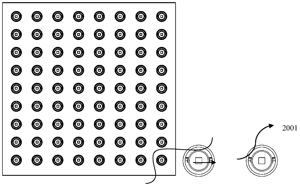
[0058] Referring to the above-mentioned main steps of the quick detection operation of the liquid crystal antenna panel, fix the sample of the liquid crystal antenna panel with 72 units, light up the LED wicks corresponding to each unit in turn starting from unit 1, and test the brightness data transmitted through each unit . Test the luminance data of the detection sample in the state of no voltage and the state of applying the maximum voltage of 15V, and collect the images of the corresponding units at the same time. According to the analysis of the measured luminance data, it was found that the luminance values ​​of the middle four units numbered 20, 28, 29 and 37 exceeded 15% of the average value with no voltage applied and with the maximum voltage applied, and the detection was found to be abnormal. The images collected by units numbered 20, 28, 29, and 37 are retrieved, and it can be clearly seen that the images of units 28 and 29 are slightly darker and slightly yellowi...

Embodiment 2

[0060] In order to supplement Example 1 for further detection, it is necessary to change the angle and polarization state of the outgoing light to check the abnormality of units 20 and 37. The angles between the outgoing light directions of the LED wicks corresponding to units 20 and 37 and the sample surface were adjusted to 25° and -25° respectively, and the same image acquisition was carried out under the conditions of no voltage applied and a maximum voltage of 15V respectively. It is found that there is a faint shadow on the image of unit 37. Continue to adjust the angle to 10° for detection. It is found that the area of ​​the weak shadow becomes larger. Therefore, it is speculated that there is a small foreign object on the edge of the unit graphic of unit 37, and this foreign object is located at The opaque graphics area at the edge. Unit 20 was unremarkable. The next step is to disassemble and assemble the polarizing film and rotate the angle of the polarizing film of...


PUM


Abstract

The invention discloses a rapid detection device for a liquid crystal antenna panel. The rapid detection device comprises six systems, namely a light source generation system, a light path regulationand control system, a detection sample fixing system, a polarizing film disassembly and assembly and motion control system, an optical signal collection and conversion system and a to-be-detected liquid crystal antenna panel. A light source component array is designed, each light source component can be independently switched on and off according to detection requirements, and detection of different emergent light angles and fine and comprehensive optical detection of liquid crystal products are achieved by adjusting parameters such as the emergent light angle and the emergent light polarization state of the light source. According to the device, a photoelectric signal detector and an image acquisition camera (CCD) are combined for use, so detection results can be accurately classified andobtained, an automatic online detection mode is provided, and the detection speed is high. The detection identification degree of the to-be-detected liquid crystal antenna panel is effectively improved, and the variety and detection efficiency of product defect detection of the liquid crystal antenna panel in production and manufacturing are greatly increased.

Description

technical field [0001] The invention relates to the field of antenna technology and liquid crystal panels, in particular to a quick detection device for liquid crystal antenna panels. Background technique [0002] With the urgent needs of wireless interconnection such as Internet of Things, 5G and satellite communication services and the rapid development of technologies, the demand for antenna function enhancement, quantity scale and cost reduction is more urgent. For this reason, electronically scanned (ESA) phased array antennas should be used However, compared with traditional mechanically steered antennas, electronically scanned (ESA) phased array antennas have significant advantages such as fast response, compact size, and easy operation and maintenance. [0003] The main implementation methods of electronically scanned (ESA) phased array antennas include microelectromechanical system (MEMS) technology, semiconductor integrated microwave circuit (MMIC) chip technology ...

Claims


Application Information

Patent Timeline
Patent Type & Authority Applications(China)
IPC IPC(8): G01N21/95G01N21/01G01M11/02
CPCG01M11/02G01M11/0285G01N21/01G01N21/95G01N2021/0112G01N2021/9513
Inventor 修威徐琦田海燕杨光
Owner BEIJING HUAMETA TECH CO LTD
Why Eureka
Try Eureka