
Flowing boiling immersion type liquid cooling device

An immersion, liquid-cooled technology, applied in the direction of instruments, electrical digital data processing, digital data processing components, etc., can solve the problems of excessive use of cooling liquid, easy volatilization of cooling liquid, and slow flow rate of servers, so as to reduce the consumption and avoid The local temperature is too high and the effect of improving the cooling effect

Active Publication Date: 2020-06-30
SUZHOU LANGCHAO INTELLIGENT TECH CO LTD
View PDF10 Cites 12 Cited by
  • Summary
  • Abstract
  • Description
  • Claims
  • Application Information

AI Technical Summary

Problems solved by technology

The disadvantage is that usually, when designing this type of cooling, a huge cooling box is designed, and multiple groups of servers are placed in the box for centralized cooling.
Due to the large size of the cabinet, the flow rate of the server liquid through the server is slow, and the convective heat transfer coefficient is small. For areas with high power density such as chips, the heat transfer capacity is limited, and local hot spots are still prone to occur. At the same time, an oversized cabinet will carry Too much coolant will cause excessive use of coolant, and at the same time, it will also cause the coolant to be easily volatilized and wasted

Method used


Image

  • Flowing boiling immersion type liquid cooling device
  • Flowing boiling immersion type liquid cooling device
  • Flowing boiling immersion type liquid cooling device

Examples


Embodiment 1

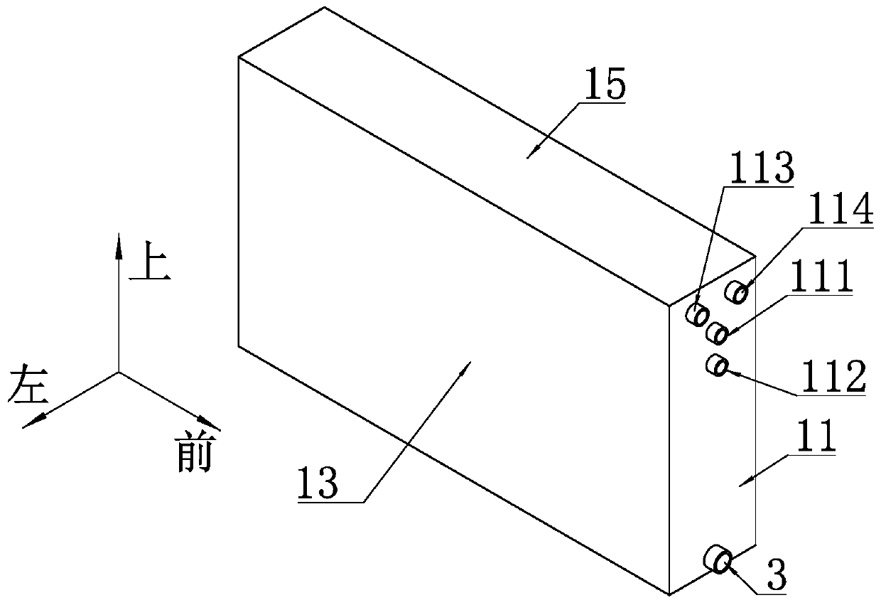
[0044] For the convenience of description, the coordinate system is defined as figure 2 shown.

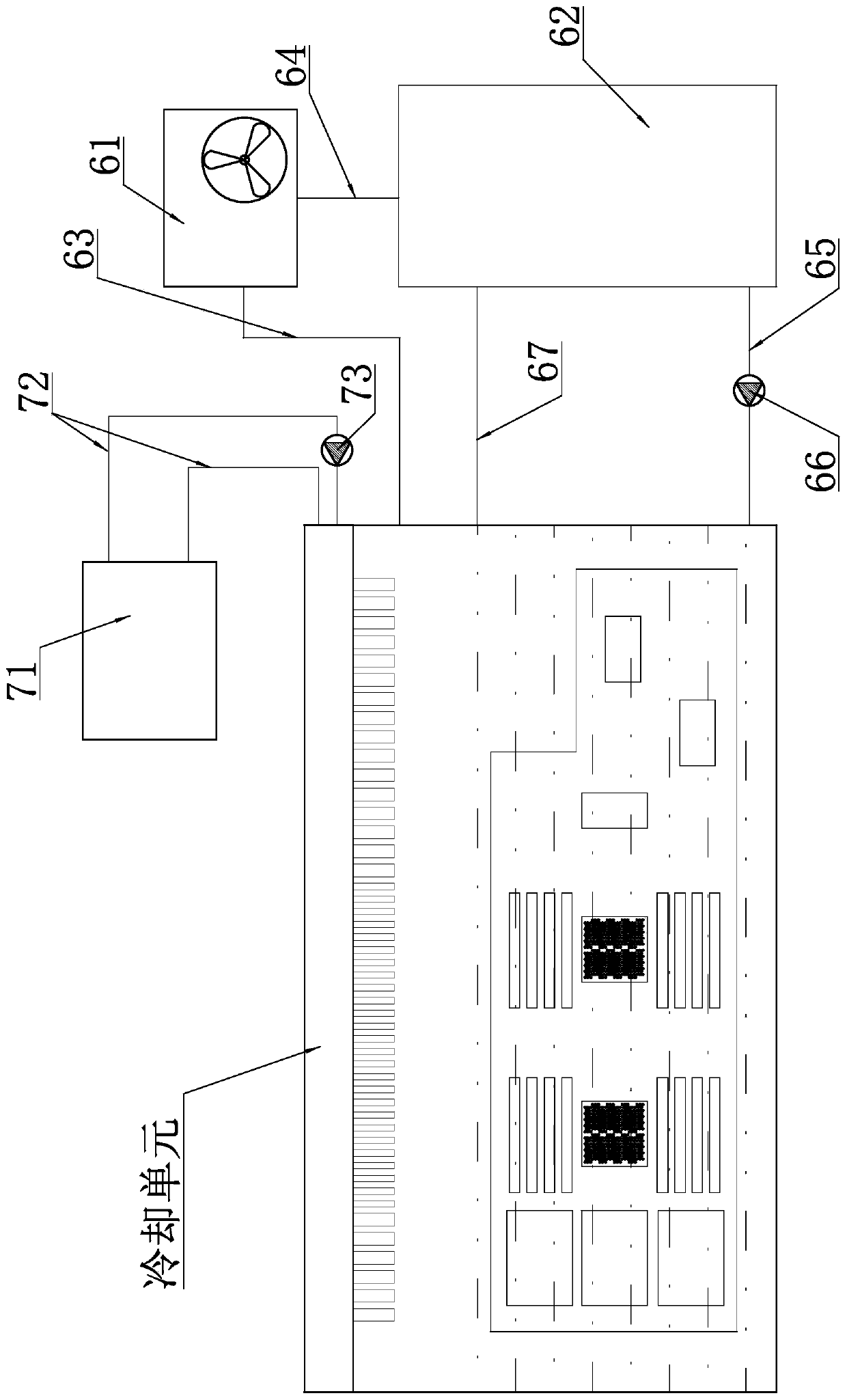
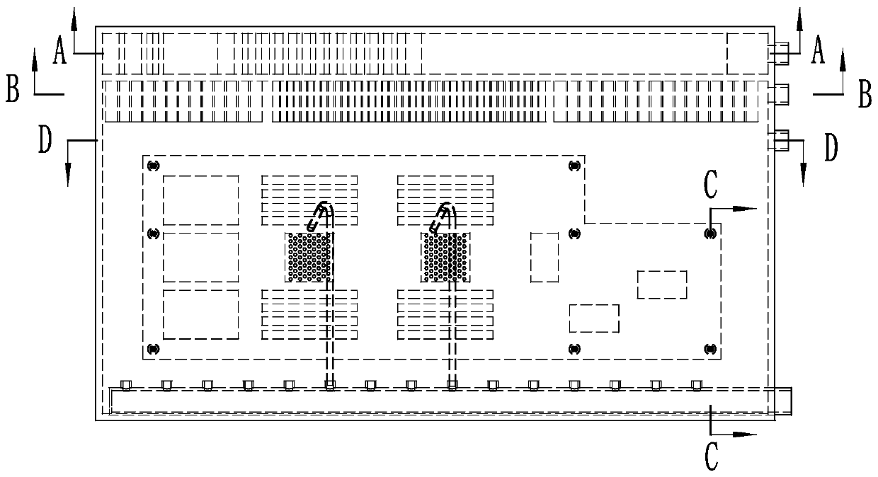
[0045] Such as figure 1 As shown, a flow boiling immersion liquid cooling device includes a cooling unit, such as image 3 with Figure 8 As shown, the cooling unit includes a square box composed of a front side plate 11, a rear side plate 12, a left side plate 13, a right side plate 14, a top plate 15 and a bottom plate 16, and the box is filled with A coolant that undergoes a phase change. As a specific implementation, the cooling liquid described in this embodiment adopts fluorinated liquid.

[0046] The main board 2 is fixedly arranged in the box, and the main board 2 is immersed in the cooling liquid.

[0047] As a specific implementation, the main board 2 described in this embodiment is fixedly arranged on the right side plate 14 of the box body, and is fixedly connected with the right side plate 14 of the box body through locking screws 5 .

[0048]An air return port,...

Embodiment 2

[0065] Such as Figure 12 As shown, the left side plate 13 and the right side plate 14 of the box body are respectively provided with a main board 2, and the main board 2 is fixedly connected with the box body through screws, and the liquid inlet pipe 3 is located at the two sides. Between two described main boards 2, all the other structures are the same as embodiment one.


PUM


Abstract

The invention discloses a flowing boiling immersion type liquid cooling device, and relates to the technical field of server hardware equipment. The device comprises a cooling unit, the cooling unit comprises a square box body, and the box body is filled with cooling liquid capable of generating phase change. A mainboard is fixedly arranged on a left side plate and / or a right side plate of the boxbody, and the mainboard is immersed in the cooling liquid. An air return port, an overflow port and a liquid inlet pipe are sequentially arranged on a front side plate of the box body from top to bottom, wherein the air return port is connected with an inlet of an air-cooled condenser, an outlet of the air-cooled condenser is connected with a first inlet of the liquid storage tank, the overflow port is connected with a second inlet of the liquid storage tank, an outlet of the liquid storage tank is connected with the liquid inlet pipe through a liquid inlet pipeline, and a first circulating pump is arranged on the liquid inlet pipeline. According to the system, the use amount of cooling liquid is effectively reduced, the size of the whole equipment is reduced, the fluidity of the coolingliquid is improved, and then the heat dissipation effect is improved.

Description

technical field [0001] The invention relates to the technical field of server hardware equipment, in particular to a flowing boiling submerged liquid cooling device. Background technique [0002] With the acceleration of technological innovation in my country's data center industry, the localization level of data centers and servers has been continuously improved, and more and more products have emerged. According to Moore's Law, the power consumption of server chips is increasing year by year. In the next two years, the power consumption of CPU chips will exceed 300W, and the power consumption of GPU chips will exceed 500W. Excessive chip power consumption leads to the use of air-cooled cooling methods, and it is difficult to completely dissipate the heat of the chip, which is easy to generate local hot spots, causing the server chip temperature to be too high, causing downtime and other hazards. Therefore, new cooling methods for servers and chips have become an important...

Claims


Application Information

Patent Timeline
IPC IPC(8): G06F1/20
CPCG06F1/20
Inventor 李金波刘志
Owner SUZHOU LANGCHAO INTELLIGENT TECH CO LTD
Learn More