Orthopedic surgical navigation positioning device and C-arm X-ray equipment

A technology for navigation and positioning and orthopaedic surgery, applied in the field of medical treatment, can solve the problems of inaccurate positioning of X-rays, increase the dose of X-rays of patients, and adverse health, so as to improve the accuracy of irradiation, reduce the impact on the body, and improve the position of the body. The effect of flexibility

Inactive Publication Date: 2020-07-03
胡增永
View PDF0 Cites 1 Cited by
  • Summary
  • Abstract
  • Description
  • Claims
  • Application Information

AI Technical Summary

Problems solved by technology

[0003] However, the existing C-arm X-ray machine cannot accurately locate the central position of the X-ray during X-ray transmission, resulting in the need for multiple positionings to be able to transmit to the exact position during transmission, which wastes time and increases the The dose of X-rays irradiated to the patient is not conducive to physical health

Method used


Image

  • Orthopedic surgical navigation positioning device and C-arm X-ray equipment
  • Orthopedic surgical navigation positioning device and C-arm X-ray equipment
  • Orthopedic surgical navigation positioning device and C-arm X-ray equipment

Examples


Embodiment 1

[0028] Such as Figure 1-Figure 2 A navigation and positioning device for orthopedic surgery is shown, the positioning device is suitable for C-arm X-ray equipment,

[0029] Such as figure 1 and figure 2 As shown, the C-arm X-ray equipment includes an X-ray emitter 6 and an X-ray receiver 7. The X-ray emitter 6 emits X-rays toward the X-ray receiver 7. X-rays are used in medical diagnosis, mainly based on the penetration of X-rays. Permeation, differential absorption, photosensitivity and fluorescence. When X-rays pass through the human body, they are absorbed in different degrees. For example, the amount of X-rays absorbed by bones is more than that absorbed by muscles, so the amount of X-rays after passing through the human body is different, which carries the density distribution of various parts of the human body. Information, the strength of the fluorescent effect or photosensitive effect caused on the fluorescent screen or on the photographic film is quite different,...

Embodiment 2

[0041] Embodiment 2 is a further improvement to Embodiment 1.

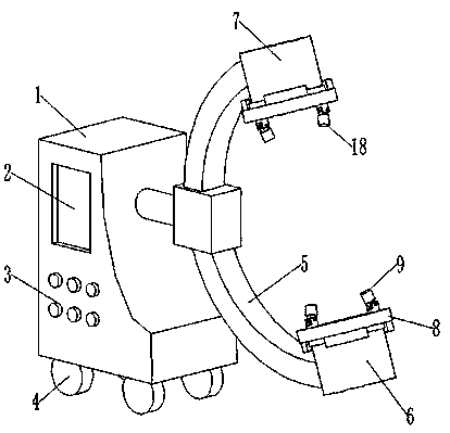
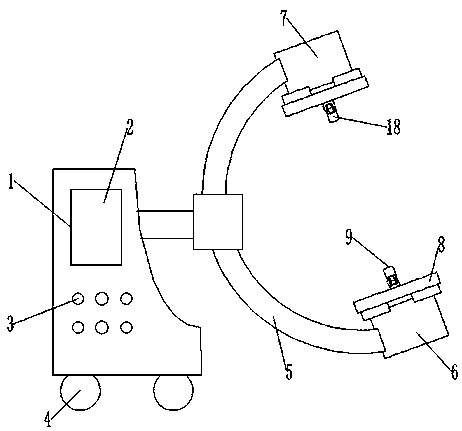
[0042] Such as figure 1 and figure 2 As shown, a C-arm X-ray equipment includes a console 1, a C-shaped carrier 5, an X-ray emitter 6, an X-ray receiver 7 and a positioning device.

[0043] Such as figure 1 and figure 2 As shown, the console 1 is provided with a display screen 2 and control buttons 3, so as to facilitate the operation of the medical staff, and the bottom of the console 1 is provided with a roller 4, so as to facilitate the movement of the device.

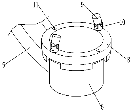
[0044] Such as figure 2 As shown, the C-shaped carrier 5 is connected to the console 1, one end of the C-shaped carrier 5 is connected with an X-ray, the other end of the C-shaped carrier 5 is connected with an X-ray receiver 7, and the X-ray emitter 6 faces the X-ray The receiver 7 emits X-rays, and the X-ray emitter 6 or the X-ray receiver 7 is detachably installed with a positioning device. The positioning device includes a mounting frame 8 a...


PUM


Abstract

The invention relates to an orthopedic surgical navigation positioning device and C-arm X-ray equipment. The positioning device comprises a mounting frame and a plurality of laser emitter groups; themounting frame is of an annular structure, the mounting frame is adapted to be arranged outside an X-ray emitter or an X-ray receiver in a sleeving mode, the mounting frame is detachably connected with the X-ray emitter or the X-ray receiver, and the mounting frame can rotate around the centerline of the X-ray emitter or the centerline of the X-ray receiver; the plurality of laser emitter groups are arranged on the mounting frame at intervals along the circumferential direction of the mounting frame; each laser emitter group comprises a laser emitter and a supporting base; the supporting baseis detachably connected with the mounting frame; the laser emitter is rotatably mounted on the supporting base in a damping mode. The laser emitter is adapted to emit laser light. The laser light formdifferent laser emitters are crossed, and the intersection point is located on the central axis of the X-ray beam of the C-arm X-ray equipment.

Description

technical field [0001] The invention relates to the field of medical technology, in particular to a navigation and positioning device for orthopedic surgery and a C-arm X-ray device. Background technique [0002] C-arm X-ray machine: As the name implies, the equipment consists of a C-shaped frame, a tube that produces X-rays, an image intensifier and a CCD camera for collecting images, and a workstation for image processing. It is mainly used for radiography and photography in various operations. [0003] However, the existing C-arm X-ray machine cannot accurately locate the central position of the X-ray during X-ray transmission, resulting in the need for multiple positionings to be able to transmit to the exact position during transmission, which wastes time and increases the The dose of X-rays that patients are exposed to is not conducive to their health. Contents of the invention [0004] The present invention aims to solve at least one of the technical problems exis...

Claims


Application Information

Patent Timeline
Patent Type & Authority Applications(China)
IPC IPC(8): A61B34/20A61B6/00
CPCA61B6/44A61B6/4441A61B6/505A61B34/20A61B2034/2055A61B2034/2065
Inventor 胡增永
Owner 胡增永
Why Eureka
Try Eureka