Shaking type machine tool cooling liquid efficient production equipment

A technology for production equipment and cooling liquid, applied in the directions of shaking/oscillating/vibrating mixers, mixers, dissolving, etc., can solve the problems of low mixing efficiency, poor lubrication performance, poor finished product effect, etc., to improve mixing efficiency and uniformity. performance, ensuring mixing efficiency and uniformity

Pending Publication Date: 2020-07-03
李明军
View PDF8 Cites 4 Cited by
  • Summary
  • Abstract
  • Description
  • Claims
  • Application Information

AI Technical Summary

Problems solved by technology

[0006] 1. The first category is traditional completely water-soluble coolant (containing a large amount of nitrite), emulsion or soapy water (containing a large amount of engine oil and nitrite, etc.), mineral oil and animal and vegetable oil; this type of cooling Liquid is mainly low cost and poor lubricating performance
[0007] 2. The second category is foreign imported cooling liquid, which has three types: complet

Method used


Image

  • Shaking type machine tool cooling liquid efficient production equipment
  • Shaking type machine tool cooling liquid efficient production equipment
  • Shaking type machine tool cooling liquid efficient production equipment

Examples


Embodiment 1

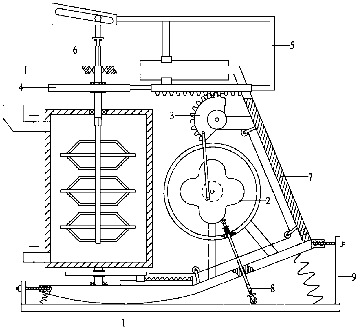
[0062] Referring to the accompanying drawings, a high-efficiency production equipment for swaying machine tool coolant includes a frame assembly 1, a sway assembly 2, a transmission assembly 3 and a mixing assembly 4;

[0063] The frame assembly 1 includes a bottom plate 101, a shaking seat 102, a support plate 103, a return spring 104, a side plate 105, a top plate 106 and a mixing tank 107; Connect with back-moving spring 104; The bottom of rocking seat 102 is an arc surface, and overlaps with base plate 101; Rocking seat 102 right end is connected with support plate 103, also is connected with return spring 104 between the right end of support plate 103 bottom and base plate 101; Top plate 106 is arranged above the shaking seat 102, and the right end of the top plate 106 and the right end of the support plate 103 are connected by the side plate 105; the mixing tank 107 is arranged between the top plate 106 and the shaking seat 102, and the bottom is connected with the shakin...

Embodiment 2

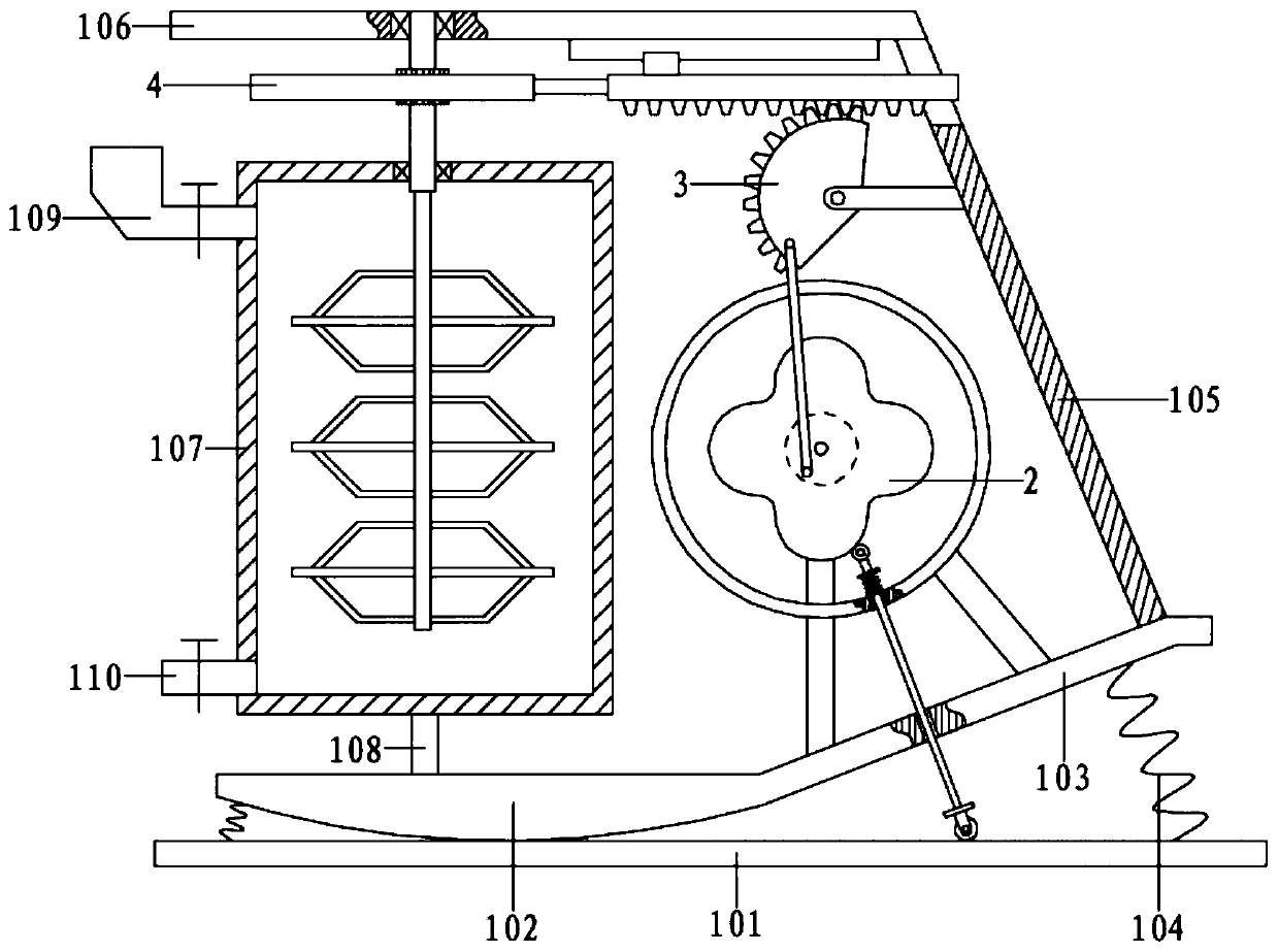
[0065] Referring to the accompanying drawings, a high-efficiency production equipment for swaying machine tool coolant includes a frame assembly 1, a sway assembly 2, a transmission assembly 3 and a mixing assembly 4;

[0066] The frame assembly 1 includes a bottom plate 101, a shaking seat 102, a support plate 103, a return spring 104, a side plate 105, a top plate 106 and a mixing tank 107; Connect with back-moving spring 104; The bottom of rocking seat 102 is an arc surface, and overlaps with base plate 101; Rocking seat 102 right end is connected with support plate 103, also is connected with return spring 104 between the right end of support plate 103 bottom and base plate 101; Top plate 106 is arranged above the shaking seat 102, and the right end of the top plate 106 and the right end of the support plate 103 are connected by the side plate 105; the mixing tank 107 is arranged between the top plate 106 and the shaking seat 102, and the bottom is connected with the shakin...

Embodiment 3

[0078] The difference from Example 2 is that

[0079] It also includes a reciprocating assembly 5 and a lifting assembly 6; the reciprocating assembly 5 is arranged above the top plate 106, and the right end of the reciprocating assembly 5 cooperates with the mixing assembly 4 through the elevating assembly 6.

[0080] The reciprocating assembly 5 includes No. 3 connecting rod 501, No. 4 connecting rod 502, No. 2 slider 503, No. 2 slide rail 504, moving block 505 and inclined groove 506;

[0081] The right end of the No. 1 rack 304 passes through the side plate 105 and is connected with the No. 3 connecting rod 501; the No. 3 connecting rod 501 is higher than the top plate 106 after being bent, and the bending section extends to the left and is connected with the moving block 505; There is No. 2 slide rail 504, and the bending section is connected with No. 2 slide block 503 through No. 4 connecting rod 502, and No. 2 slide block 503 is slidingly connected with No. 2 slide rail...


PUM


Abstract

The invention relates to the technical field of machine tool cooling liquid production, in particular to shaking type machine tool cooling liquid efficient production equipment. A servo motor is adopted to drive a cam to rotate, a roller acts with the cam under the matching action of a first spring, so that a force application rod reciprocates, a force application rod drives the roller to press abottom plate and apply a force to the bottom plate, a supporting plate is lifted or falls down through cooperation with a reset spring, a shaking base synchronously swings and drives a mixing tank above the shaking base to shake along with the shaking base, raw materials in the mixing tank are automatically mixed, when the cam rotates, a first connecting rod drives a half gear to swing back and forth, so that the first rack moves back and forth in the direction of a first sliding rail, a second connecting rod drives a second rack to move synchronously, the second rack drives a first driven gear to drive a rotating part to rotate, so that the stirring shaft rotates along with the first driven gear, the stirring part is driven to stir and mix the raw materials in the mixing tank, and the mixing efficiency and uniformity are guaranteed in cooperation with shaking of the mixing tank.

Description

technical field [0001] The invention relates to the technical field of machine tool coolant production, in particular to a swaying high-efficiency machine tool coolant production equipment, more specifically, a shakeable machine tool coolant high-efficiency mixing equipment. Background technique [0002] Machine tool (English name: machine tool) refers to a machine that manufactures a machine, also known as a machine tool or a machine tool, and is customarily referred to as a machine tool. Generally divided into metal cutting machine tools, forging machine tools and woodworking machine tools. There are many ways to process mechanical parts in modern machinery manufacturing: in addition to cutting, there are also casting, forging, welding, stamping, extrusion, etc. The final machining is done by cutting on the machine tool. Machine tools play an important role in the modernization of the national economy. [0003] Coolant needs to be applied in time during machine tool pro...

Claims


Application Information

Patent Timeline
IPC IPC(8): B01F11/00
CPCB01F31/449B01F31/441
Inventor 李明军
Owner 李明军
Why Eureka
Try Eureka