
A double-head chamfering grinding device for permanent magnet ferrite

A permanent magnet ferrite and chamfering technology, which is applied in the direction of grinding/polishing safety devices, grinding slides, grinding racks, etc. Oxygen body yield rate decline and other problems, to achieve the effect of high yield rate, chamfering yield rate, chamfering processing precision improvement

Active Publication Date: 2022-05-20
HENGDIAN GRP DMEGC MAGNETICS CO LTD
View PDF8 Cites 0 Cited by
  • Summary
  • Abstract
  • Description
  • Claims
  • Application Information

AI Technical Summary

Problems solved by technology

[0003] The present invention overcomes the chamfering process of the permanent magnet oxygen body by using a single-head chamfering machine twice successively in the prior art to complete the double-head chamfering of the permanent magnet oxygen body, which leads to a decrease in the efficiency of the chamfering process and two successive positionings The technical problem that leads to the decline of the yield rate of the finished permanent magnet ferrite, provides a permanent magnet ferrite double-head chamfer grinding device, which can realize the synchronous automatic forming of the permanent magnet ferrite double-head chamfer, and the permanent magnet ferrite The processing efficiency of double-end chamfering is greatly improved. In addition, only one positioning of the permanent magnet oxygen body is required during the processing process, and the yield rate of the finished permanent magnet oxygen body is high.

Method used


Image

  • A double-head chamfering grinding device for permanent magnet ferrite
  • A double-head chamfering grinding device for permanent magnet ferrite
  • A double-head chamfering grinding device for permanent magnet ferrite

Examples


Embodiment

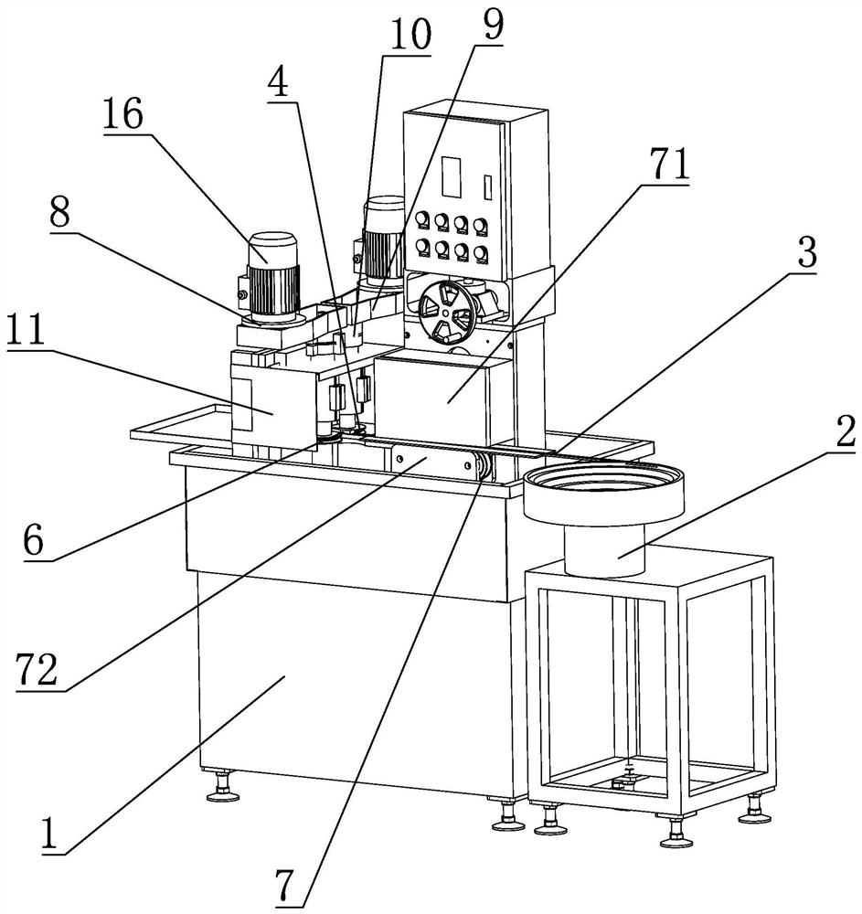
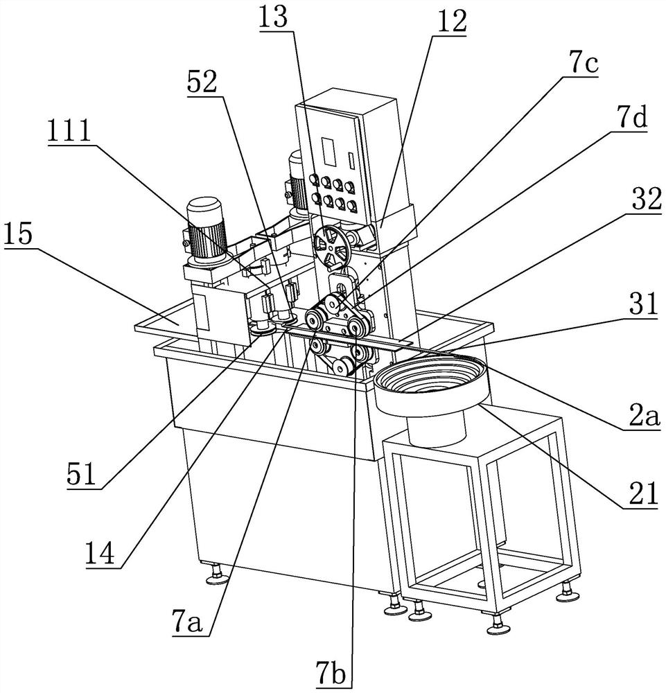
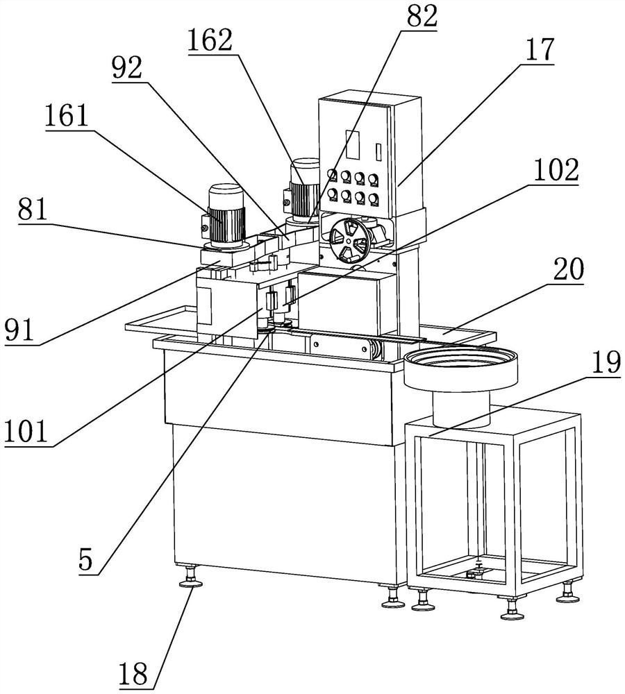
[0036] Such as Figure 1 to Figure 3 As shown, a permanent magnet ferrite double-head chamfering grinding device includes a frame 1, a feeding mechanism 2 is provided on one side of the frame, a conveying member 3 and a chamfering member 4 are arranged on the frame, and the chamfering member Including the forming grinding wheel 5 arranged in gaps, the forming grinding wheel rotates synchronously under the drive of the driving member, the feeding mechanism aligns the permanent magnet ferrite 6 and then transports it to the conveying member, and when the permanent magnet ferrite is conveyed to the chamfering member by the conveying member The forming grinding wheel chamfers the two ends of the permanent magnet ferrite. The frame is equipped with a horizontal pushing member 7 that drives the adjacent permanent magnet ferrite to fit closely. The first transverse pusher member 71 and the second transverse pusher member 72 on both sides; the multi-groove pulley 8 driven by the motor...


PUM


Abstract

A double-head chamfering grinding device for permanent magnet ferrite, which aims to solve the problem of using a single-head chamfering machine to chamfer the permanent magnet ferrite twice successively to complete the double-head chamfering of the permanent magnet ferrite. , resulting in a reduction in the efficiency of the chamfering process and a technical problem that the yield rate of the finished permanent magnet ferrite is reduced by two positionings. The invention comprises a frame, one side of the frame is provided with a feeding mechanism, and the frame is provided with a conveying member and a chamfering member, and the chamfering member includes forming grinding wheels arranged in gaps, and the forming grinding wheels rotate synchronously under the drive of the driving member. The feeding mechanism arranges the permanent magnet ferrite in an orientation and then transports it to the conveying member. When the permanent magnet ferrite is conveyed from the conveying member to the chamfering member, the forming grinding wheel performs chamfering processing on both ends of the permanent magnet ferrite. The drive frame is equipped with Adjacent permanent magnet ferrites are bonded to closely arranged transverse pushing members, and the transverse pushing members include a first transverse pushing member and a second transverse pushing member respectively located on the upper and lower sides of the conveying member.

Description

technical field [0001] The invention relates to the technical field of magnetic material processing, in particular to a permanent magnet ferrite double-head chamfering grinding device. Background technique [0002] At present, the chamfering of permanent magnet ferrite squares is usually done manually, and the chamfering method is ground on one side. This method usually has high labor intensity, low efficiency and high cost. With the diversification of market products, there are more and more permanent magnet ferrite products with double-head chamfering, but the processing of double-head chamfering products is still completed by single-head chamfering head, which means that double-head chamfering products need to go through two successive The second single-head chamfering process; taking the patent application number CN 201510274150.6 as an example, the patent discloses an automatic production line for arc-shaped permanent magnet ferrite chamfering and its implementation met...

Claims


Application Information

Patent Timeline
Patent Type & Authority Patents(China)
IPC IPC(8): B24B9/06B24B41/00B24B41/02B24B27/00B24B55/04B24B55/00H01F41/02
CPCB24B9/06B24B41/005B24B41/02B24B27/0076B24B55/04B24B55/00H01F41/0253
Inventor 包一心刘文根胡晖民
Owner HENGDIAN GRP DMEGC MAGNETICS CO LTD
Features
  • Generate Ideas
  • Intellectual Property
  • Life Sciences
  • Materials
  • Tech Scout
  • Unparalleled Data Quality
  • Higher Quality Content
  • 60% Fewer Hallucinations
Learn More