
Device for treating high-concentration organic wastewater by catalyzing hydrothermal gasification

A technology of organic wastewater and water distribution device, which is applied in the direction of oxidation water/sewage treatment, mechanical details of gasification device, water/sewage treatment, etc. It can solve environmental problems, reduce safety risks, reduce energy consumption, and enhance use effects Effect

Active Publication Date: 2020-07-03
NANJING UNIV +1
View PDF6 Cites 6 Cited by
  • Summary
  • Abstract
  • Description
  • Claims
  • Application Information

AI Technical Summary

Problems solved by technology

[0002] Industrial production has become an important part of driving economic development, but the "three wastes" produced in the industrial production process will also cause very serious environmental problems
However, there is no report on the treatment of high-concentration organic wastewater by catalytic hydrothermal gasification technology

Method used


Image

  • Device for treating high-concentration organic wastewater by catalyzing hydrothermal gasification
  • Device for treating high-concentration organic wastewater by catalyzing hydrothermal gasification
  • Device for treating high-concentration organic wastewater by catalyzing hydrothermal gasification

Examples


Embodiment 1

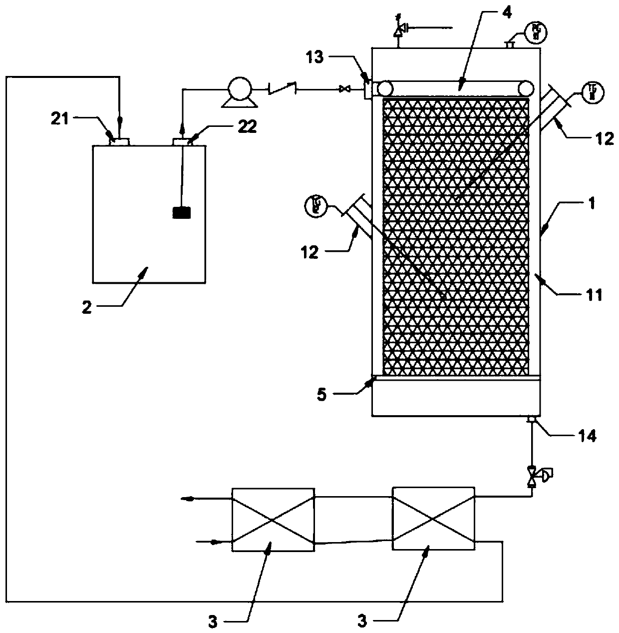
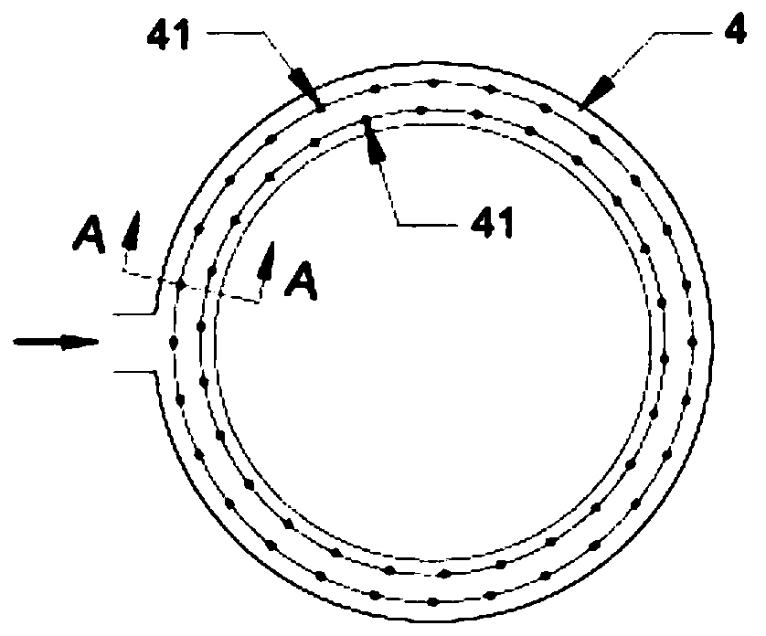
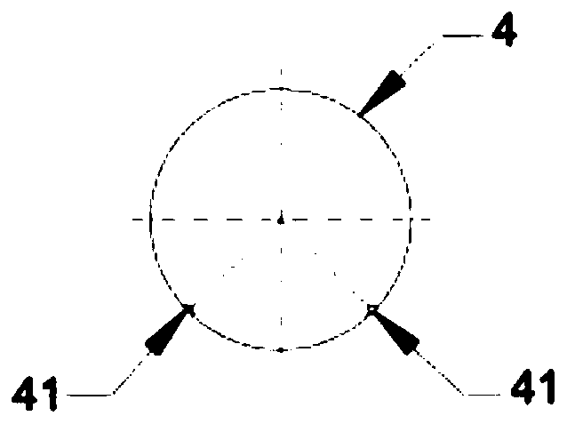
[0042] Such as figure 1 As shown, a catalytic hydrothermal gasification treatment device for high-concentration organic wastewater mainly includes a CHG reactor 1, a wastewater temporary storage tank 2, and a condensation heat exchanger 3; the CHG reactor 1 mainly includes a casing 11, a thermocouple 12, a water distribution device, packing support, housing 11 is respectively provided with feed inlet 13, gas outlet 14, packing support is used to support the catalyst packing and is arranged in the shell 11, the water distribution device is arranged in the shell 11 above the catalyst packing, thermocouple 12 Inserted on the side wall of the shell 11 and extended into the catalyst packing; the condensing heat exchanger 3 communicates with the gas outlet 14 through the back pressure valve and the pipeline, and the liquid inlet 21 of the waste water temporary storage tank 2 communicates with the condensate through the high-pressure feed pump and the pipeline. The heat exchanger 3 i...

Embodiment 2

[0047] The present embodiment is basically the same as Embodiment 1, and its difference lies in the difference of the packing support, such as Figure 4 , 6 , 7, the packing support is specifically a circulating packing support 6, which includes a packing mesh plate 61, a filler conveying column 62, and a packing conduit 63; The tapered top packing net plate 611, the middle packing net plate 612 and the bottom packing net plate 613 with an inverted conical section, such as Figure 4 , 8 As shown, the center of the top packing net plate 611 and the middle packing net plate 612 are respectively provided with a through hole 614 for placing the packing conveying column 62, and the circumferential side walls of the top packing net plate 611, the flat packing net plate 612 and the shell 11 The inner wall is disassembled and connected, and the through hole 614 is provided with a U-shaped annular clamping groove 615, which is used for matching and docking with the snap ring 64 neste...

Embodiment 3

[0053] This embodiment is basically the same as Embodiment 2, the difference is that the transmission assembly 7 is different, such as Figure 10-12As shown, the transmission assembly 7 is a water distribution device and a rotating rod 73. The water distribution device includes a water distribution pan 72. The interior of the water distribution pan 72 is hollow, and is divided into a central disc structure 721 and a water distribution ring structure located at the circumference of the central disc structure. 722; the central disc structure 721 bottom surface center of the water distribution tray 72 is provided with a turning bar 73 to be connected with the turning block 65, and the turning wheel 74 is connected with the turning bar 73 in the water distributing tray 72, and the turning wheel 74 circumference places are provided with multiple A rotating blade 741 matched with the size of the water distribution ring, the rotating wheel 74 at the rear of the rotating blade 741 is p...


PUM

PropertyMeasurementUnit
specific surface areaaaaaaaaaaa

Abstract

The invention discloses a device for treating high-concentration organic wastewater through catalytic hydrothermal gasification. The device mainly comprises a CHG reactor, a wastewater temporary storage tank and a condensation heat exchanger, wherein the CHG reactor mainly comprises a shell, a thermocouple, a water distribution device and a filler bracket, the shell is provided with a feed port and a gas outlet, the filler bracket is used for supporting a catalyst filler and is arranged in the shell, the water distribution device is arranged in the shell above the catalyst filler, and the thermocouple is inserted into the side wall of the shell and extends into the catalyst filler. The condensation heat exchanger is communicated with the air outlet through a back pressure valve and a pipeline, the liquid inlet of the wastewater temporary storage tank is connected with the condensation heat exchanger through a high-pressure feeding pump and a pipeline, and the liquid outlet of the wastewater temporary storage tank is connected with the feeding port through the high-pressure feeding pump and a pipeline. The device can quickly convert high-concentration organic wastewater into clean energy or harmless gas at a low temperature under the action of a catalyst, greatly reduces the energy consumption in the treatment process, improves the treatment efficiency, and has potential application prospects.

Description

technical field [0001] The invention relates to the technical field of wastewater treatment equipment, in particular to a catalytic hydrothermal gasification device for treating high-concentration organic wastewater. Background technique [0002] Industrial production has become an important part of driving economic development, but the "three wastes" produced in the industrial production process will also cause very serious environmental problems. Among them, industrial organic wastewater, especially high-concentration organic wastewater that is difficult to biodegrade has become a recognized problem in the environmental field. Especially in recent years, with the development of large-scale and integrated industrial production, the types and discharges of waste water have been increasing, and the pollution of water bodies has become increasingly widespread and serious, seriously threatening human health. Therefore, it is of great significance to develop new high-concentrat...

Claims


Application Information

Patent Timeline
Patent Type & Authority Applications(China)
IPC IPC(8): C02F1/02C02F1/72C02F101/30
CPCC02F1/025C02F1/725C02F2101/30C10J2300/0979C10J3/78C10J2200/06C10J2300/0986C10J2200/09C10J2200/36Y02P20/52C02F2301/06
Inventor 吕路王林平芮杰黄前霖徐敬生张炜铭潘丙才
Owner NANJING UNIV
Learn More