
Electroplating wastewater zero-liquid discharge system and process

A technology of electroplating wastewater and discharge system, which is applied in the direction of metallurgical wastewater treatment, electrolysis components, electrolysis process, etc., can solve the problems of affecting the filtering effect, reducing the processing efficiency, causing mutagenesis, etc., so as to solve the problem of filter clogging, improve the processing efficiency and The effect of the filter effect

Pending Publication Date: 2021-06-15
洛阳国联新材料研究院有限公司 +1
View PDF8 Cites 0 Cited by
  • Summary
  • Abstract
  • Description
  • Claims
  • Application Information

AI Technical Summary

Problems solved by technology

The water quality of electroplating wastewater is complex, and its composition is difficult to control. It contains heavy metal ions such as chromium, cadmium, nickel, copper, zinc, gold, silver, and cyanide, and some are highly toxic substances that are carcinogenic, teratogenic, and mutagenic.
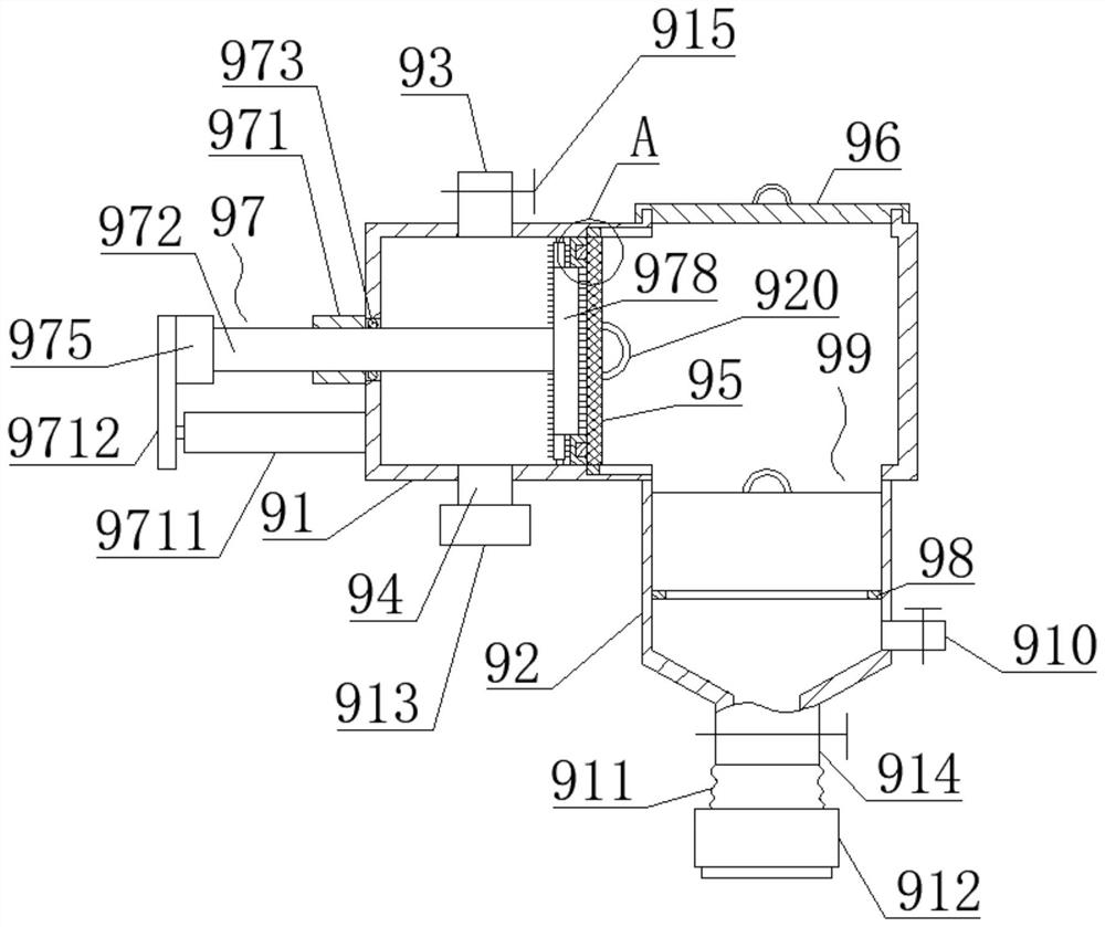
[0003] The existing electroplating wastewater treatment still has liquid discharge, and the discharged liquid still has the risk of pollution; and in the process of electroplating wastewater discharge treatment, the supernatant after the heavy metal precipitation treatment needs to be treated, which requires the use of activated carbon filters, and The existing activated carbon filter often has the problem of filter clogging, which greatly reduces the treatment efficiency, and after a long time of use, there will be dirt attached to the inner wall of the filter, affecting the filtering effect

Method used


Image

  • Electroplating wastewater zero-liquid discharge system and process
  • Electroplating wastewater zero-liquid discharge system and process
  • Electroplating wastewater zero-liquid discharge system and process

Examples


Embodiment Construction

[0029] The present invention will be further described in conjunction with the accompanying drawings and specific embodiments.

[0030]The content not described in detail in this specification belongs to the prior art known to those skilled in the art. In describing the present invention, it is to be understood that the terms "center", "upper", "lower", "front", "rear", "left", "right", "vertical", "horizontal", The orientation or positional relationship indicated by "top", "bottom", "inner", "outer", "clockwise", "counterclockwise", etc. are based on the orientation or positional relationship shown in the drawings, and are only for the convenience of describing this The invention and the simplified description do not indicate or imply that the device or element referred to must have a specific orientation, be constructed and operate in a specific orientation, and thus should not be construed as limiting the present invention. In addition, the terms "first", "second", "third"...


PUM


Abstract

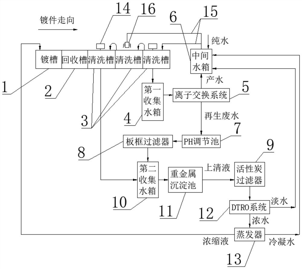
The invention discloses an electroplating wastewater zero-liquid discharge system and process, and belongs to the technical field of electroplating wastewater processing.The electroplating wastewater zero-liquid discharge system is characterized in that a last cleaning tank in the moving direction of a plated part is communicated with a first collecting water tank, and the water outlet end of the first collecting water tank is communicated with the water inlet end of an ion exchange system; and the water producing end of the ion exchange system is communicated with a middle water tank, the water outlet end of the plate and frame filter and the first cleaning tank in the moving direction of the plated part are both communicated with the second collecting water tank, the water outlet end of the second collecting water tank is communicated with the heavy metal settling pond, and the supernatant water outlet end of the heavy metal settling pond is communicated with the activated carbon filter. The concentrated liquid end of the evaporator recycles concentrated liquid to the plating tank through a pipeline, the fresh water end of the DTRO and the condensate water end of the evaporator are both communicated with the middle water tank, and the water outlet end of the middle water tank supplies water to the at least two cleaning tanks. According to the electroplating wastewater zero-liquid discharge system and the electroplating wastewater zero-liquid discharge process, the treated liquid is completely recycled, zero liquid discharge is realized, and the processing efficiency is high.

Description

technical field [0001] The invention belongs to the technical field of electroplating wastewater treatment, and in particular relates to a zero-liquid discharge system and process for electroplating wastewater. Background technique [0002] The sources of electroplating wastewater are generally: (1) plating cleaning water; (2) waste electroplating solution; (3) other wastewater, including washing the floor of the workshop, scrubbing plate washing water, condensed water from ventilation equipment, and leakage from plating tanks. Or various tank liquids and drainages of "running, popping, dripping, and leaking" caused by improper operation and management; (4) Equipment cooling water, which has not been polluted except for the temperature rise during use. The water quality and quantity of electroplating wastewater are related to the process conditions of electroplating production, production load, operation management and water use methods and other factors. The water quality ...

Claims


Application Information

Patent Timeline
Patent Type & Authority Applications(China)
IPC IPC(8): C02F9/10C25D17/00C25D21/22C02F103/16C02F101/20
CPCC02F9/00C25D17/00C25D21/22C02F2103/16C02F1/42C02F1/66C02F1/001C02F1/52C02F2101/20C02F1/441C02F1/04C02F2303/14C02F1/283
Inventor 李迎军夏天华
Owner 洛阳国联新材料研究院有限公司
Learn More