A magnetic coupling device for downhole signal transmission

A signal transmission and magnetic coupling technology, applied in buildings and other directions, can solve the problems of weak magnetic field strength, signal loss, affecting signal strength, etc., and achieve the effect of enhancing magnetic induction strength, reducing signal loss, and preventing eddy current loss.

Active Publication Date: 2021-10-08
HUAZHONG UNIV OF SCI & TECH
View PDF9 Cites 0 Cited by
  • Summary
  • Abstract
  • Description
  • Claims
  • Application Information

AI Technical Summary

Problems solved by technology

The downhole environment is complex and changeable, and the close contact between the launch device and the formation medium cannot be guaranteed, so the transmission efficiency cannot be guaranteed
2) The composition of the formation medium in the oil well is very complex, some components have high conductivity, and the signal will have a large attenuation during the transmission process, thus affecting the transmission quality of the signal
[0004] The magnetic coupling method has the following problems: Since the equipment needs to work downhole, the oil well head is only slightly thicker than the tubing, and the coil needs to go downhole with the tubing, which puts strict requirements on the size of the overall structure of the coil and the installation and recovery of the coil
The existing magnetic coupling coils can generate weak magnetic field strength under the limitation of existing working conditions and device size, which cannot meet the requirements of signal transmission under complex geological conditions
When using the principle of magnetic coupling for signal transmission, choose to use low-frequency signals for transmission, and the large capacitance in the coil will cause signal loss
In addition, the underground is a harsh environment of high temperature and high pressure, so the shell of the coil needs to have high strength. Although the commonly used metal and alloy materials can guarantee the strength, they will produce eddy current effects in the metal shell, which will affect the signal. strength

Method used


Image

  • A magnetic coupling device for downhole signal transmission
  • A magnetic coupling device for downhole signal transmission
  • A magnetic coupling device for downhole signal transmission

Examples


Embodiment Construction

[0027] In order to make the object, technical solution and advantages of the present invention clearer, the present invention will be further described in detail below in conjunction with the accompanying drawings and embodiments. It should be understood that the specific embodiments described here are only used to explain the present invention, not to limit the present invention. In addition, the technical features involved in the various embodiments of the present invention described below can be combined with each other as long as they do not constitute a conflict with each other.

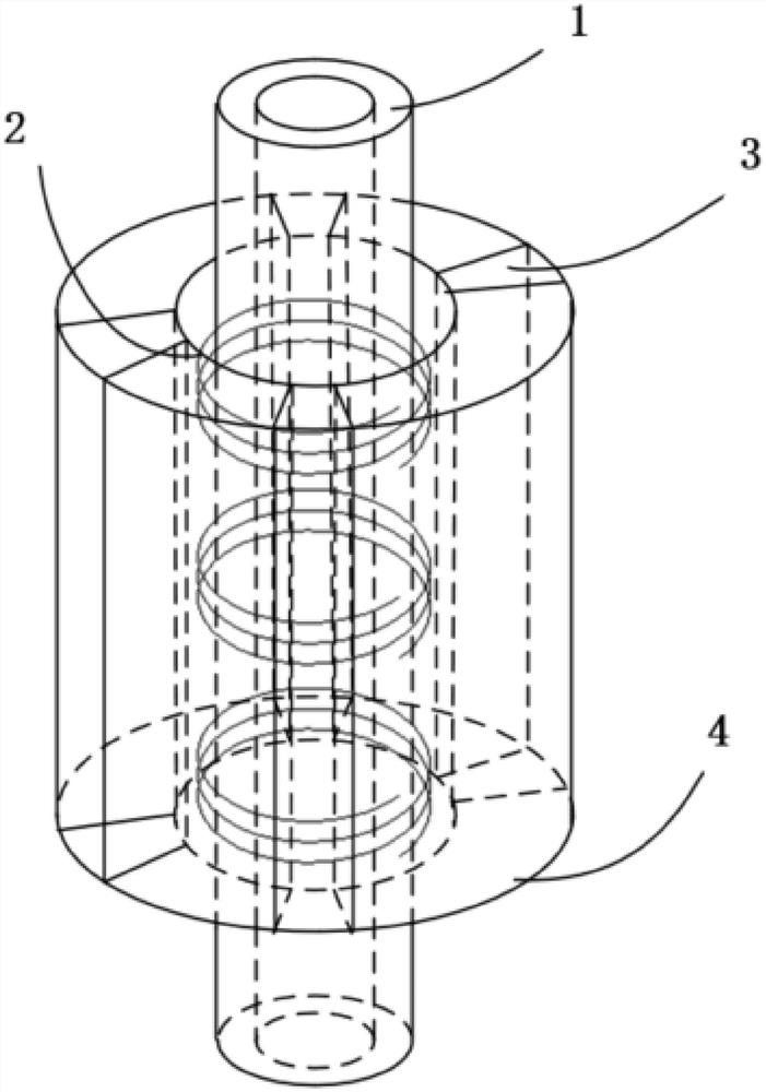
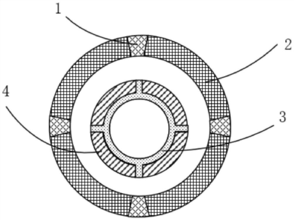
[0028] The invention provides a magnetic coupling device for downhole signal transmission, comprising: a transmitting module and a receiving module with the same structure; the transmitting module transmits downhole measurement data to the receiving module in a wireless manner through the principle of magnetic coupling; the receiving module transmits The downhole measurement data is uploaded to ...


PUM


Abstract

The invention discloses a magnetic coupling device for underground signal transmission, which belongs to the field of underground transmission. Including: a transmitting module and a receiving module with the same structure; the transmitting module transmits the downhole measurement data to the receiving module wirelessly through the principle of magnetic coupling; the receiving module uploads the downhole measurement data to the ground system; the transmitting module includes: concave pole tubular Main body, fan-shaped strip-shaped iron core, spaced coil and fence-shaped metal casing; multiple grooves are evenly distributed on the surface of the concave-type tubular body, and fan-shaped long strip-shaped iron core is fixed in each groove; spaced coils are equally spaced Segmentally wound on the outer surface of the concave pole tubular body; the fence-shaped metal shell is wrapped outside the spaced coil, and the surface is evenly distributed with multiple fan-shaped slits, and each fan-shaped slit is filled with non-metallic materials. The invention can enhance the strength of the magnetic field under the same working conditions and greatly reduce the attenuation of signals, thereby realizing high-performance and high-quality wireless transmission underground.

Description

technical field [0001] The invention belongs to the technical field of downhole transmission, and more particularly relates to a magnetic coupling device for downhole signal transmission. Background technique [0002] In the petroleum industry, the exploitation of oil fields requires drilling, and after drilling, it is necessary to complete the measurement of downhole temperature, pressure, geological and other information. Due to the harsh downhole environment, the traditional wired transmission method is impossible, and the wireless transmission method has been widely used. application and promotion. To ensure the stable and reliable transmission of measurement data, it is necessary to start from the following two aspects: 1) enhance the strength of the transmission signal; 2) control the loss of the signal during transmission. [0003] The existing wireless transmission methods mainly include the electric field coupling method and the magnetic coupling method. Among them...

Claims


Application Information

Patent Timeline
Patent Type & Authority Patents(China)
IPC IPC(8): E21B47/13
Inventor 陈庆张成涛余沐阳刘昶胡皓然杨思谛李红斌
Owner HUAZHONG UNIV OF SCI & TECH
Why Eureka
Try Eureka