

Tunnel cold-proof and freezing-proof system in alpine regions
A technology for alpine regions and tunnels, applied in tunnels, tunnel linings, underground chambers, etc., it can solve the problems of unsustainable and stable energy supply, difficult to obtain, etc.
- Summary
- Abstract
- Description
- Claims
- Application Information
AI Technical Summary
Problems solved by technology
Method used
Image

Examples
Embodiment 1
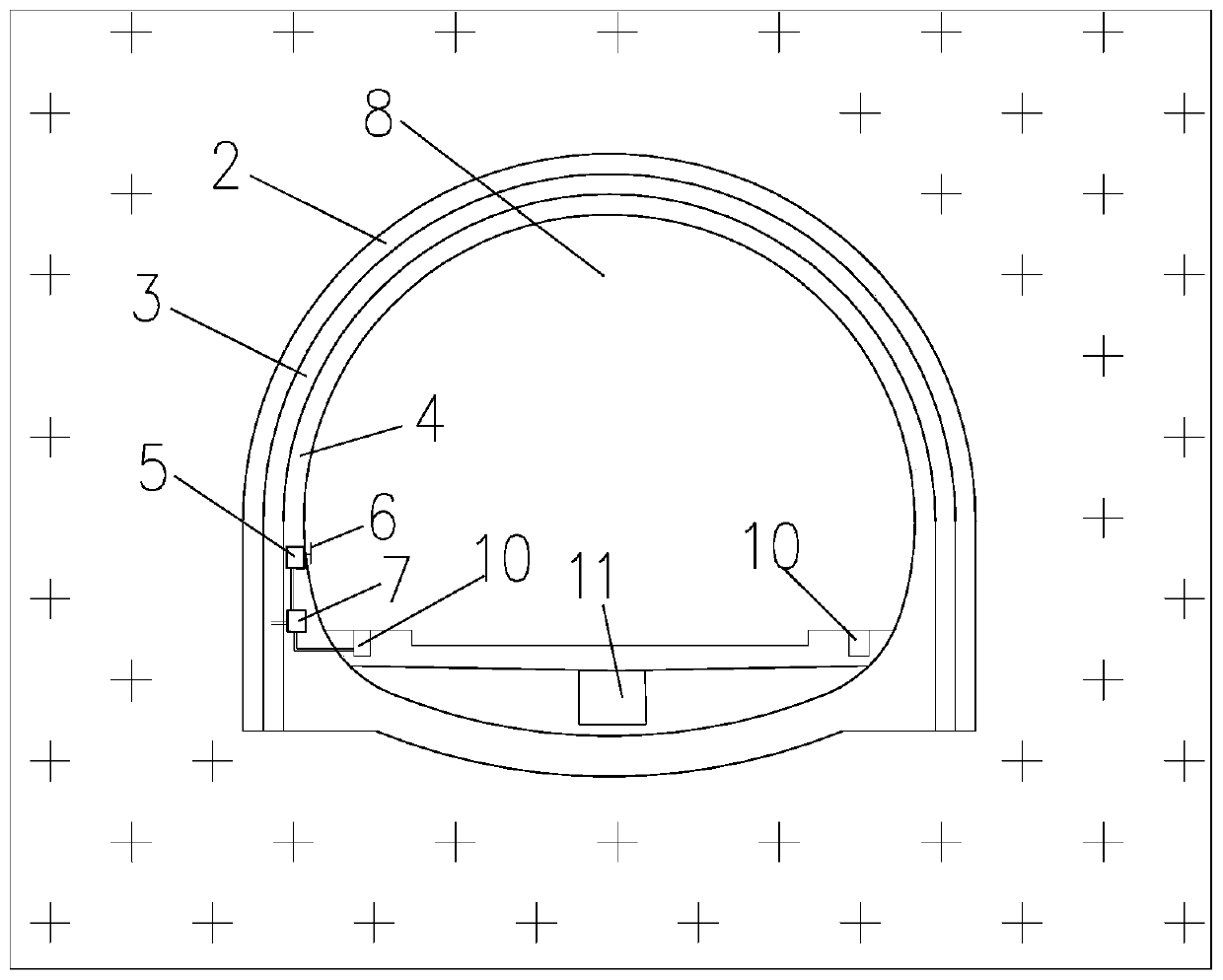
[0069] see figure 1 . An embodiment of the present invention provides a cold-proof and anti-freeze system for a tunnel 8 in an alpine region, which includes a fan 6, a generator 5, an anti-freeze layer 3 and an electric heating element.
[0070] Wherein, the fan 6 is arranged in the tunnel 8 , the generator 5 is connected to the fan 6 , and the antifreeze layer 3 is arranged between the primary support 2 and the secondary lining 4 of the tunnel 8 .
[0071] The electric heating element is electrically connected to the generator 5 , and the electric heating element is arranged in the drainage system of the tunnel 8 and / or in the antifreeze layer 3 , and the drainage system includes a central ditch 11 and a side ditch 10 . That is: the electric heating element can be arranged only in the drainage system of the tunnel 8, also can be arranged only in the antifreeze layer 3, can also be arranged in the drainage system of the tunnel 8 and the antifreeze layer 3 at the same time.
...
Embodiment 2
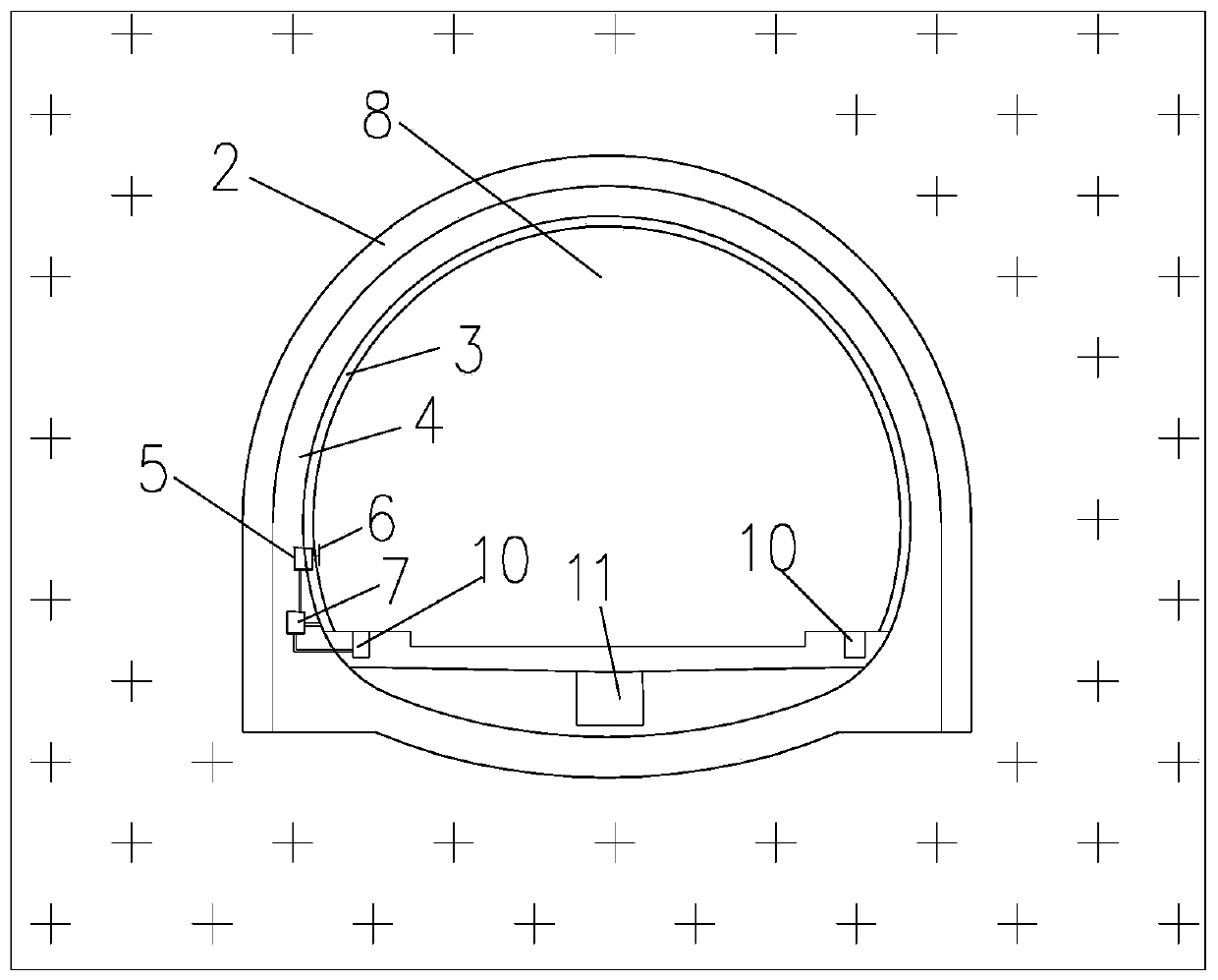
[0089] see figure 2 . The embodiment of the present invention provides a kind of anti-cold and anti-freeze system for the tunnel 8 in the alpine region. side.
Embodiment 3
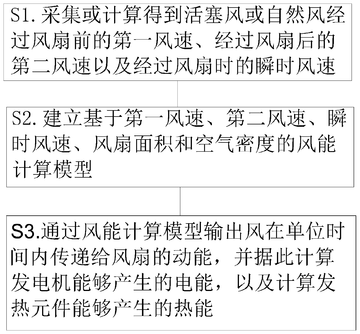
[0091] see image 3 , the present embodiment provides a heat energy calculation method for the cold and antifreeze system of the tunnel 8 in the alpine region, which is used to calculate the heat energy that can be generated by the cold and antifreeze system of the tunnel 8 in the alpine region in Embodiment 1 when the wind passes through the tunnel 8 , the thermal energy calculation method includes the following steps:
[0092] S1. Collect or calculate the first wind speed before the piston wind or natural wind passes through the fan 6, the second wind speed after passing through the fan 6, and the instantaneous wind speed when passing through the fan 6;
[0093] Specifically, the first wind speed may be obtained by measurement or by calculation.
[0094] When the train passes through the tunnel 8, the first wind speed of the piston wind before the fan 6 can be calculated in the following manner:
[0095] When calculating with constant flow:
[0096]
[0097] When calcu...
PUM
 Abstract
Description
Claims
Application Information