Rogowski coil

A Rogowski coil and coil technology, applied in the direction of coil, voltage/current isolation, measuring device, etc., can solve the problems of influence, weak voltage signal, large error, etc., and achieve the effect of accurate measurement and accurate small current

Inactive Publication Date: 2020-07-03
HEBEI WINSUN ELECTRONICS TECH
View PDF5 Cites 3 Cited by
  • Summary
  • Abstract
  • Description
  • Claims
  • Application Information

AI Technical Summary

Problems solved by technology

However, precisely because it has no iron core, the voltage signal induced by the Rogowski coil is relatively weak, and it is very susceptible to the influence of stray magnetic fields in the external environment
Therefore, the existing Rogowski coils have large errors when detecting small currents, and are only used to detect large currents.

Method used


Image

  • Rogowski coil
  • Rogowski coil
  • Rogowski coil

Examples


Embodiment Construction

[0024] In order to make the purpose, technical solution and advantages of the present application clearer, the technical solution of the present invention will be described in detail below in conjunction with the drawings and embodiments. Apparently, the described embodiments are only some of the embodiments of this application, not all of them. Based on the embodiments in the present application, all other implementation manners obtained by persons of ordinary skill in the art without creative efforts fall within the protection scope of the present application.

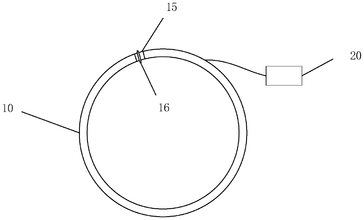
[0025] The advantage of the Rogowski coil is that the linearity is good, the coil is not saturated, and the output signal and input signal of the system are always linear, but most of them are applied to high-current application scenarios, and the detection current is generally greater than the order of magnitude of A. This method proposes an improved Technology and circuit design, realize the measurement of mA level...


PUM


Abstract

The invention discloses a Rogowski coil, comprising a coil body and a detection circuit. The coil body is used for obtaining an induction current signal, and the detection circuit is used for processing the induction current signal obtained by the coil body to obtain a specific current value. A first insulating layer is arranged on the outermost side of the coil to protect the internal structure of the coil. A coil layer is arranged inwards to induce current and generate a current signal, and the innermost side is a core wire layer and is of a structure that a framework of the coil supports the coil. A shielding layer is arranged between the first insulating layer and the coil layer to shield the interference of an external stray magnetic field, so that the coil layer is more sensitive ininduction current and is not affected by the outside. Therefore, the small current can be accurately measured.

Description

technical field [0001] The invention relates to the field of current detection, in particular to a Rogowski coil. Background technique [0002] The Rogowski coil is a hollow ring coil that can be directly sleeved on the conductor to be measured. The AC signal flowing through the conductor will generate an alternating magnetic field around the conductor, thereby inducing an AC voltage signal proportional to the current in the coil. The output voltage can be represented by the formula: Vout=Mdi / dt, where M is the mutual inductance of the coil. Di / dt is the current transformation ratio. By integrating the voltage signal output by the coil through a dedicated detection circuit, another AC voltage signal can be obtained, and the waveform of this voltage signal is used to reproduce the measured current signal. [0003] Rogowski coils have a wide range of applications. It has no special requirements on the frequency of the measured current and the size of the conductor, and it c...

Claims


Application Information

Patent Timeline
Patent Type & Authority Applications(China)
IPC IPC(8): H01F5/06H01F5/02G01R15/18G01R19/00
CPCG01R15/181G01R19/0092H01F5/02H01F5/06
Inventor 李卫荣张治奎刘国兴杨泽祥靳飞冯韶辉贾伟志李国培韩强李龙
Owner HEBEI WINSUN ELECTRONICS TECH
Why Eureka
Try Eureka