Four-layer reverse-flow type flue gas purification system

A flue gas purification system and flue gas purification technology, applied in gas treatment, chemical instruments and methods, membrane technology, etc., can solve the problems of reducing the amount of activated carbon loaded, reducing the area occupied by the purification system, and reducing costs

Pending Publication Date: 2020-07-07
BEIJING ZHTD ENVIRONMENTAL PROTECTION TECH CO LTD
View PDF0 Cites 2 Cited by
  • Summary
  • Abstract
  • Description
  • Claims
  • Application Information

AI Technical Summary

Problems solved by technology

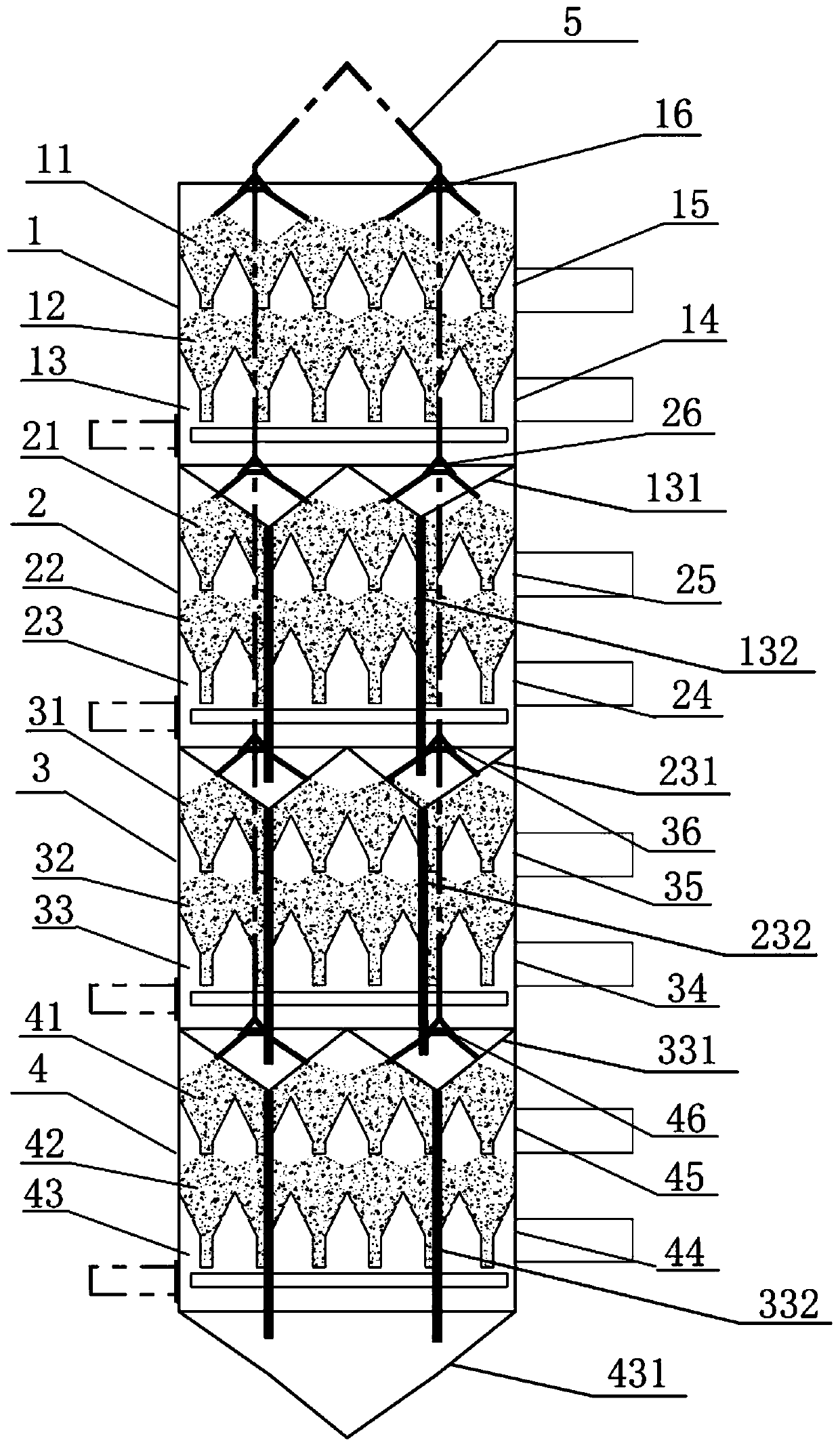
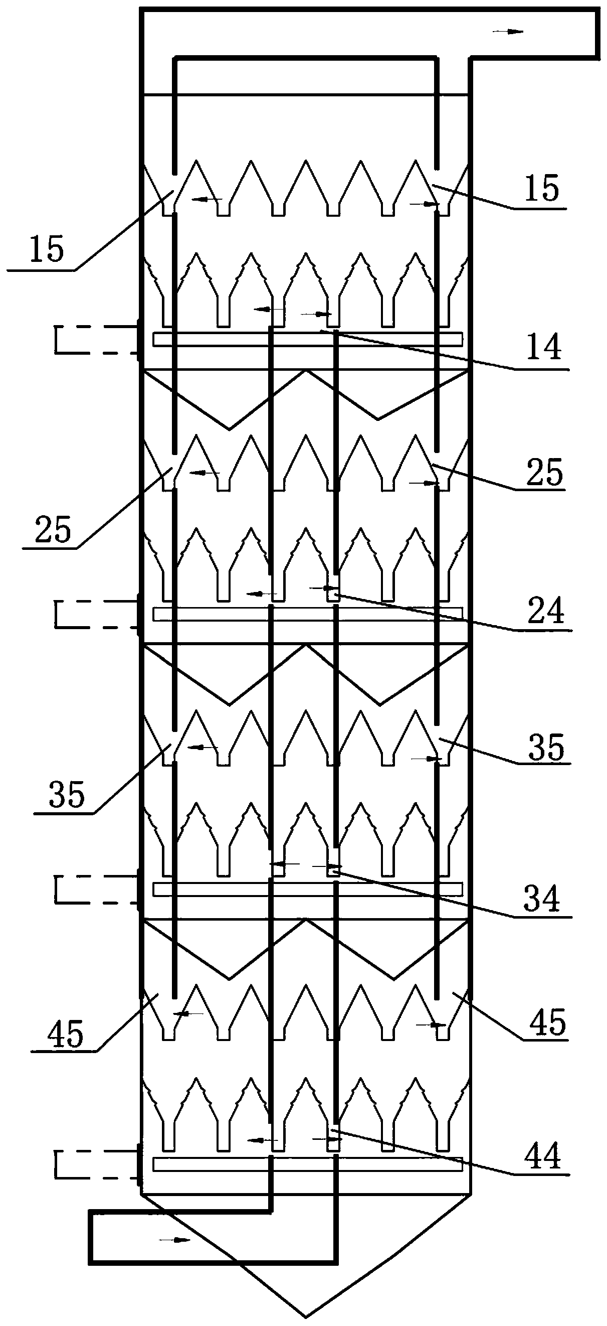
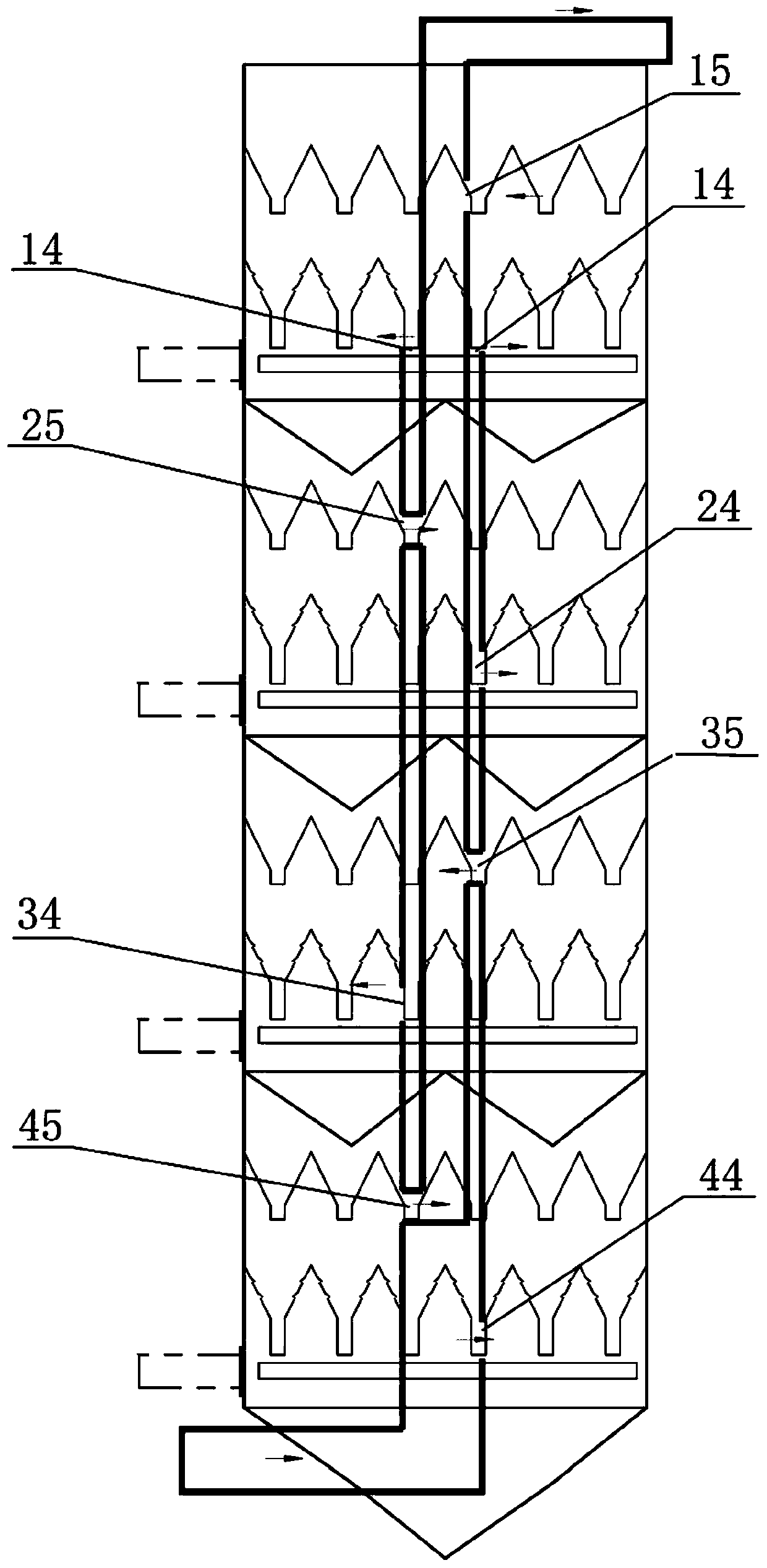
[0007] The purpose of the present invention is to provide a four-layer counter-flow flue gas purification system to at least solve the problems of the current dry desulfurization and denitrification adsorption towers for some manufacturers’ dry desulfurization, such as the applicability of the transformation, discarding the activated carbon denitrification equipment, the The two-layer desulfurization and denitrification of the adsorption tower is changed to four-layer desulfurization, and only activated carbon desulfurization is performed instead of activated carbon denitrification, which greatly reduces the loading of activated carbon and reduces the cost of investment. At the same time, the enhanced desulfurization capacity will greatly reduce the occupation of the purification system. land area

Method used


Image

  • Four-layer reverse-flow type flue gas purification system
  • Four-layer reverse-flow type flue gas purification system
  • Four-layer reverse-flow type flue gas purification system

Examples


Embodiment Construction

[0044] The present invention will be described in detail below with reference to the accompanying drawings and examples. It should be noted that, in the case of no conflict, the embodiments in the present application and the features in the embodiments can be combined with each other.

[0045] In the description of the present invention, the terms "longitudinal", "transverse", "upper", "lower", "front", "rear", "left", "right", "vertical", "horizontal", " The orientations or positional relationships indicated by "top", "bottom", etc. are based on the orientations or positional relationships shown in the drawings, and are only for the convenience of describing the present invention and do not require that the present invention must be constructed and operated in a specific orientation, so they cannot be understood as Limitations on the Invention. The terms "connected" and "connected" used in the present invention should be understood in a broad sense, for example, it can be fi...


PUM


Abstract

The invention discloses a four-layer reverse-flow type flue gas purification system. Each layer of reverse-flow type flue gas purification device comprises a material distribution layer, a desulfurization adsorption layer and a discharging layer from top to bottom, wherein the material distribution layer is used for receiving an activated carbon feeding material and uniformly distributing activated carbon on the desulfurization adsorption layer; the desulfurization adsorption layer is used for carrying out desulfurization purification treatment on flue gas; and the discharging layer is used for collecting used activated carbon and discharging. Each layer of reverse-flow type flue gas purification device further comprises a feeding port, a discharging port, a gas inlet and a gas outlet, wherein the feeding port is formed above the material distribution layer; the discharging port is formed below the discharging layer; the gas inlet is formed below the desulfurization adsorption layer; and the gas outlet is formed above the desulfurization adsorption layer and below the material distribution layer. Two layers of desulfurization and denitrification of an adsorption tower for dry desulfurization and denitrification is changed into four layers of desulfurization, so that the filling amount of activated carbon is greatly reduced, the investment cost is reduced, meanwhile, the desulfurization treatment capacity is enhanced, and the occupied area of a purification system is greatly reduced.

Description

technical field [0001] The invention belongs to the technical field of air pollutant purification equipment, in particular to a four-layer counterflow flue gas purification system. Background technique [0002] The existing mainstream denitrification processes mainly include low-temperature SCR denitrification, medium-high temperature SCR denitrification, and activated carbon denitrification. [0003] Medium and high temperature SCR denitrification is generally combined with wet desulfurization, and is mainly used for desulfurization and denitrification of boilers. Medium-temperature SCR denitrification technology is mature, and the denitrification efficiency is high, which is an ideal denitrification method. However, the by-products of wet desulfurization are difficult to deal with. [0004] Low-temperature SCR denitrification is generally used in combination with baking soda or rotary spray desulfurization methods. The low-temperature SCR denitrification process is also ...

Claims


Application Information

Patent Timeline
IPC IPC(8): B01D53/04
CPCB01D53/04B01D53/0407B01D2253/102B01D2258/0283
Inventor 刘斌邓松林刘国锋刘晓敏徐增强李转丽
Owner BEIJING ZHTD ENVIRONMENTAL PROTECTION TECH CO LTD
Why Eureka
Try Eureka