Cutting machine tool for machining metal members

A technology for cutting machine tools and metal components, applied to metal processing machine parts, metal processing equipment, manufacturing tools, etc., can solve problems such as surface damage of metal components, imperfect technology, scratches on the inner wall of metal component slots, etc.

Active Publication Date: 2020-07-07
深圳市森润精密科技有限公司
View PDF11 Cites 1 Cited by
  • Summary
  • Abstract
  • Description
  • Claims
  • Application Information

AI Technical Summary

Problems solved by technology

[0002] With the continuous progress of processing technology, more and more products and parts need to be cut, so there are many metal cutting machine tools on the market, but the current technical considerations are not perfect, and it has the following disadvantages: cutting machine tools in the process of processing A large amount of metal waste will be generated, especially when digging and grooving metal components, as the cutting progresses, the cutting waste will fall inside the metal component slot, and the equipment will drive the metal component to rotate at a high speed, resulting in waste The chip rubs aga

Method used


Image

  • Cutting machine tool for machining metal members
  • Cutting machine tool for machining metal members
  • Cutting machine tool for machining metal members

Examples


Embodiment 1

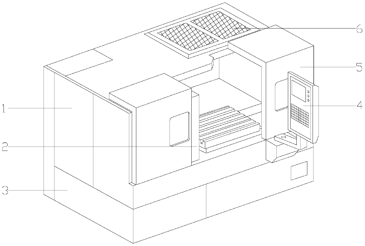
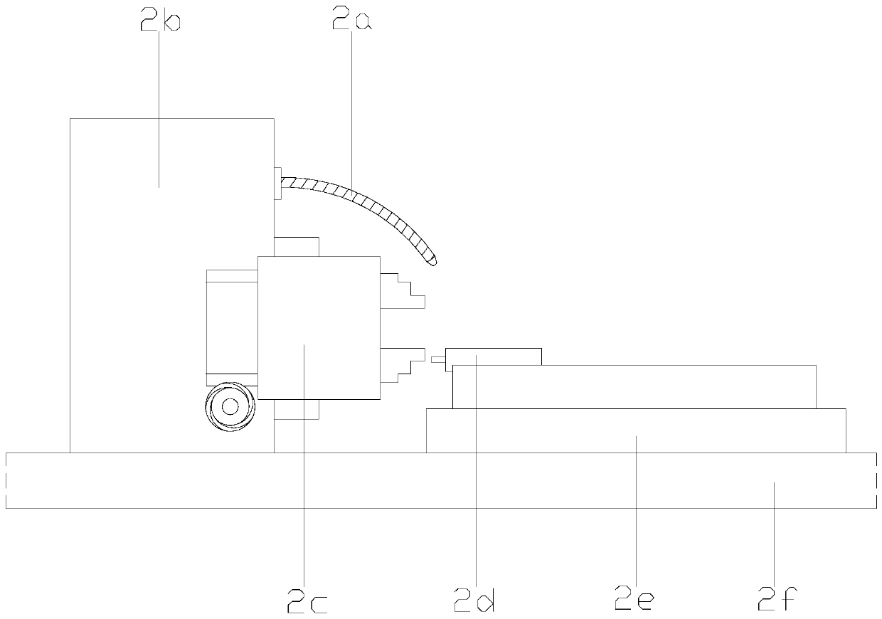
[0023] see Figure 1-Figure 4, the present invention provides a cutting machine tool for processing metal components, the structure of which includes a machine tool protective cover 1, a component cutting mechanism 2, a support base 3, an intelligent controller 4, a protective door panel 5, a dust-proof heat dissipation net 6, and the support base 3 It has a rectangular structure and is installed horizontally on the workshop floor. The machine tool protective cover 1 is located above the support base 3 and close together. The component cutting mechanism 2 is nested inside the machine tool protective cover 1. The protective door panel 5 is located on the machine tool The left and right sides of the front of the protective cover 1 adopt clearance fit. The intelligent controller 4 is fixed on the right side of the front of the machine tool protective cover 1 by bolts. The dust-proof and heat dissipation net 6 is nested on the top of the machine tool protective cover 1. Mechanism ...

Embodiment 2

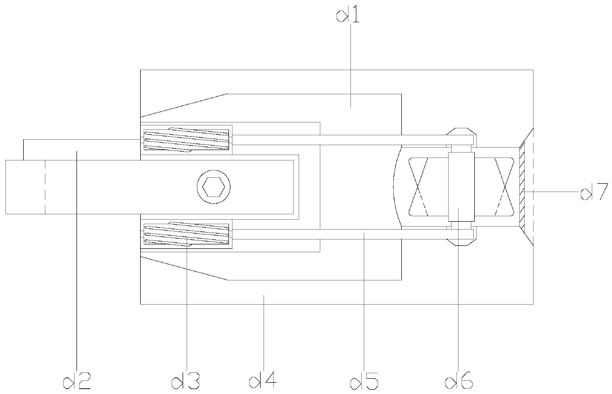
[0026] see Figure 5-Figure 6 , the automatic chip breaker d2 is composed of a fixed knob d21, a chip breaker blade d22, a waste chip guide cavity d23, a chip breaker driving structure d24, a sliding adjustment rod d25, and a chip breaker support d26. The sliding adjustment rod d25 and It is located on the left side of the cutter fixing frame d4 and has an integrated structure. The chip breaker support d26 is located on the left side of the sliding adjustment rod d25 and adopts a clearance fit. The fixed knob d21 and the sliding adjustment rod d25 are threaded. The waste guide cavity d23 is connected through the left bottom of the chip breaker support d26, the chip breaker driving structure d24 is located above the waste guide cavity d23, and the chip breaker blade d22 is located at the left end of the upper surface of the chip breaker support d26, The sliding adjustment rod d25 and the chip breaker support d26 are parallel to each other. The chip breaking driving structure d...


PUM


Abstract

The invention discloses a cutting machine tool for machining metal members. The cutting machine tool structurally comprises a machine tool protective outer cover, a member cutting mechanism, a supporting base, an intelligent controller, a protective door board and a dustproof heat dissipation net. The supporting base is of a rectangular structure and is horizontally mounted on the workshop floor,the machine tool protective outer cover is located on the upper part of the supporting base and is tightly close to the supporting base, and the member cutting mechanism is nested in the machine toolprotective outer cover. According to the cutting machine tool, by mounting a self-chip-removal cutting mechanism, in the process of machining groove holes of the metal members, sweeps in the groove holes can be effectively and rapidly discharged, the situation that the metal members are scratched due to friction of the sweeps and the metal members in the groove holes is avoided, and the machiningquality of the metal members is improved; and meanwhile, the cut sweeps can be rapidly cut off, equipment and cutters are prevented from being damaged due to the fact that the cut sweeps are wound onthe periphery of the cutters, parts and clamps, and the cutting production efficiency of the metal members is effectively improved.

Description

technical field [0001] The invention relates to the field of metal processing equipment, in particular to a cutting machine tool for processing metal components. Background technique [0002] With the continuous progress of processing technology, more and more products and parts need to be cut, so there are many metal cutting machine tools on the market, but the current technical considerations are not perfect, and it has the following disadvantages: cutting machine tools in the process of processing A large amount of metal waste will be generated, especially when digging and grooving metal components, as the cutting progresses, the cutting waste will fall inside the metal component slot, and the equipment will drive the metal component to rotate at a high speed, resulting in waste The chip rubs against the metal component in the slot, causing scratches on the inner wall of the metal component slot, which reduces the processing quality of the metal component; at the same tim...

Claims


Application Information

Patent Timeline
IPC IPC(8): B23Q1/01B23Q11/08B23Q11/00
CPCB23Q1/015B23Q11/00B23Q11/0046B23Q11/08
Inventor 王坤
Owner 深圳市森润精密科技有限公司
Why Eureka
Try Eureka