
Hydraulic buffer type tray exchange device and working method

A technology of pallet exchange and hydraulic buffering, applied in auxiliary devices, manufacturing tools, metal processing, etc.

Active Publication Date: 2020-07-07
SHANGHAI SMARTSTATE TECH CO LTD
View PDF6 Cites 1 Cited by
  • Summary
  • Abstract
  • Description
  • Claims
  • Application Information

AI Technical Summary

Problems solved by technology

The patent still has room for improvement in terms of device system precision and work performance

Method used


Image

  • Hydraulic buffer type tray exchange device and working method
  • Hydraulic buffer type tray exchange device and working method
  • Hydraulic buffer type tray exchange device and working method

Examples


Embodiment Construction

[0025] The present invention will be described in detail below in conjunction with specific embodiments. The following examples will help those skilled in the art to further understand the present invention, but do not limit the present invention in any form. It should be noted that those skilled in the art can make several changes and improvements without departing from the concept of the present invention. These all belong to the protection scope of the present invention.

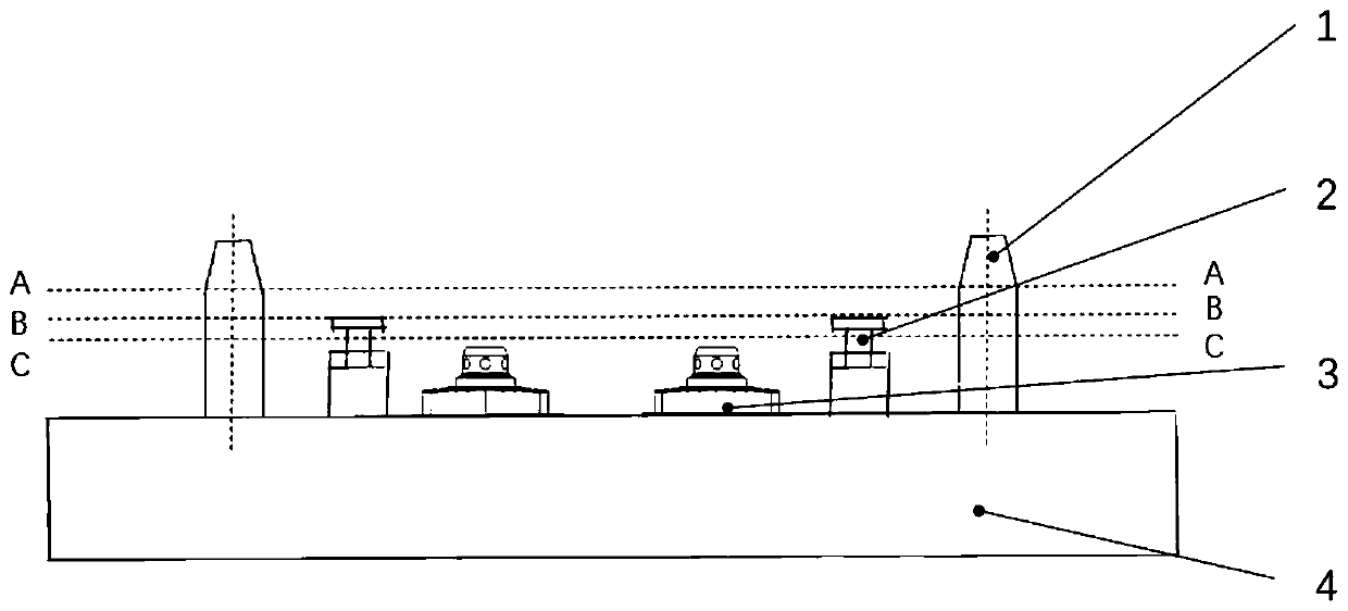
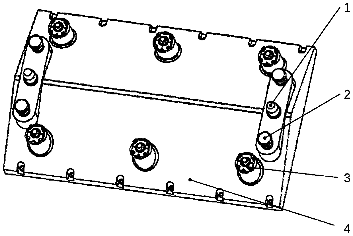
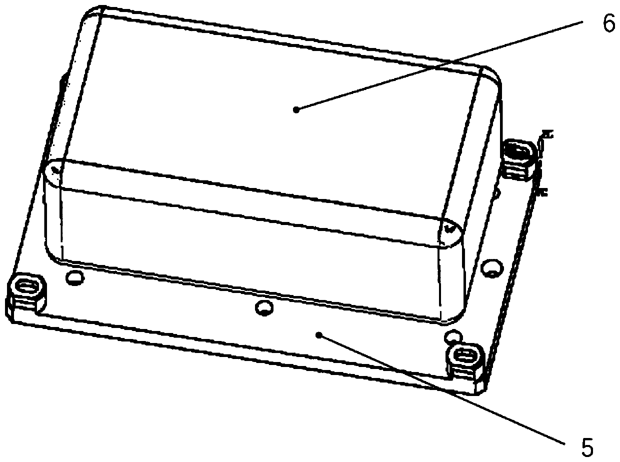
[0026] Such as Figure 1-4 As shown, a hydraulic buffer pallet exchange device provided according to the present invention includes: a fixture motherboard, a positioning pin, a hydraulic cylinder, and a zero point positioning mechanism; the fixture motherboard includes: a working surface of the fixture motherboard; the positioning pin , the hydraulic cylinder, and the zero point positioning mechanism are located on the working surface of the fixture motherboard; the fixture motherboard is installed at a...


PUM


Abstract

The invention provides a hydraulic buffer type tray exchange device and a working method. The hydraulic buffer type tray exchange device comprises a clamp mother board, locating pins, hydraulic oil cylinders and null point locating mechanisms. The clamp mother board comprises a clamp mother board working face. The locating pins, the hydraulic oil cylinders and the null point locating mechanisms are located on the clamp mother board working face. The clamp mother board is installed in any position of a target working position for tray exchange on the hydraulic buffer type tray exchange device and a clamp position for tray exchange on the hydraulic buffer type tray exchange device. The hydraulic buffer type tray exchange device and the working method thereof are suitable for large tray exchange working occasions in machining, welding and assembling industries, and the large tray exchange and installation process can be smooth and stable through a buffer function of hydraulic mechanisms in the locating process; and system locating accuracy is guaranteed, work efficiency is improved, manual control is not needed, and the tray exchange process is further automated.

Description

technical field [0001] The invention relates to the technical field of automated production lines, in particular to a hydraulic buffer pallet exchange device and a working method, especially a hydraulic buffer large pallet exchange mechanism. Background technique [0002] With the application and development of today's automated production line technology, in the machining, welding and assembly industries of aerospace, automotive molds, wind power, ships and other large parts, the manufacturing workshops mostly use flexible manufacturing systems to realize the processing of various parts and components In the process of automatic processing and assembly, pallets are widely used, especially large pallets with a size of more than 1m×1m to exchange large workpieces between different stations in the workshop. [0003] Most of the existing hoisting and positioning systems of girder trucks that perform pallet exchange work rely on manual control of the hoisting action of the girde...

Claims


Application Information

Patent Timeline
IPC IPC(8): B23Q7/00B23Q7/14B23K37/00B23P19/00
CPCB23K37/00B23P19/00B23Q7/00B23Q7/1426
Inventor 田洪峰陈坤王瑞秋
Owner SHANGHAI SMARTSTATE TECH CO LTD
Learn More