
Garbage efficient disposal facility for mechanical production

A technology for processing equipment and garbage, applied in the direction of presses, material forming presses, magnetic separation, etc., can solve the problems of slow metal decomposition, inconvenient disposal, soil hazards, etc.

Inactive Publication Date: 2020-07-07
陈洪霖
View PDF8 Cites 0 Cited by
  • Summary
  • Abstract
  • Description
  • Claims
  • Application Information

AI Technical Summary

Problems solved by technology

[0002] With the rapid development of the economy, the machining industry is becoming more and more prosperous. Machining products are distributed in various production industries. During the machining process, more metal scraps and other garbage will be generated. If such garbage is directly filled Burial, because the decomposition of metal is slow, and the substances produced after metal decomposition will cause serious harm to the soil. In addition, direct landfill will prevent metal debris from being recycled, resulting in waste of resources
[0003] At present, the metal waste generated by mechanical processing is often treated by recycling, which has achieved the sustainable development of resources. However, the metal waste produced by machinery is often collected and recycled. Due to the different metal components, it is very inconvenient to deal with after recycling.

Method used


Image

  • Garbage efficient disposal facility for mechanical production
  • Garbage efficient disposal facility for mechanical production
  • Garbage efficient disposal facility for mechanical production

Examples


Embodiment 1

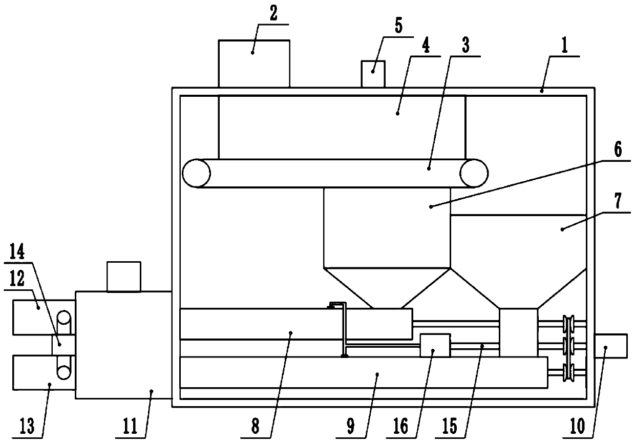
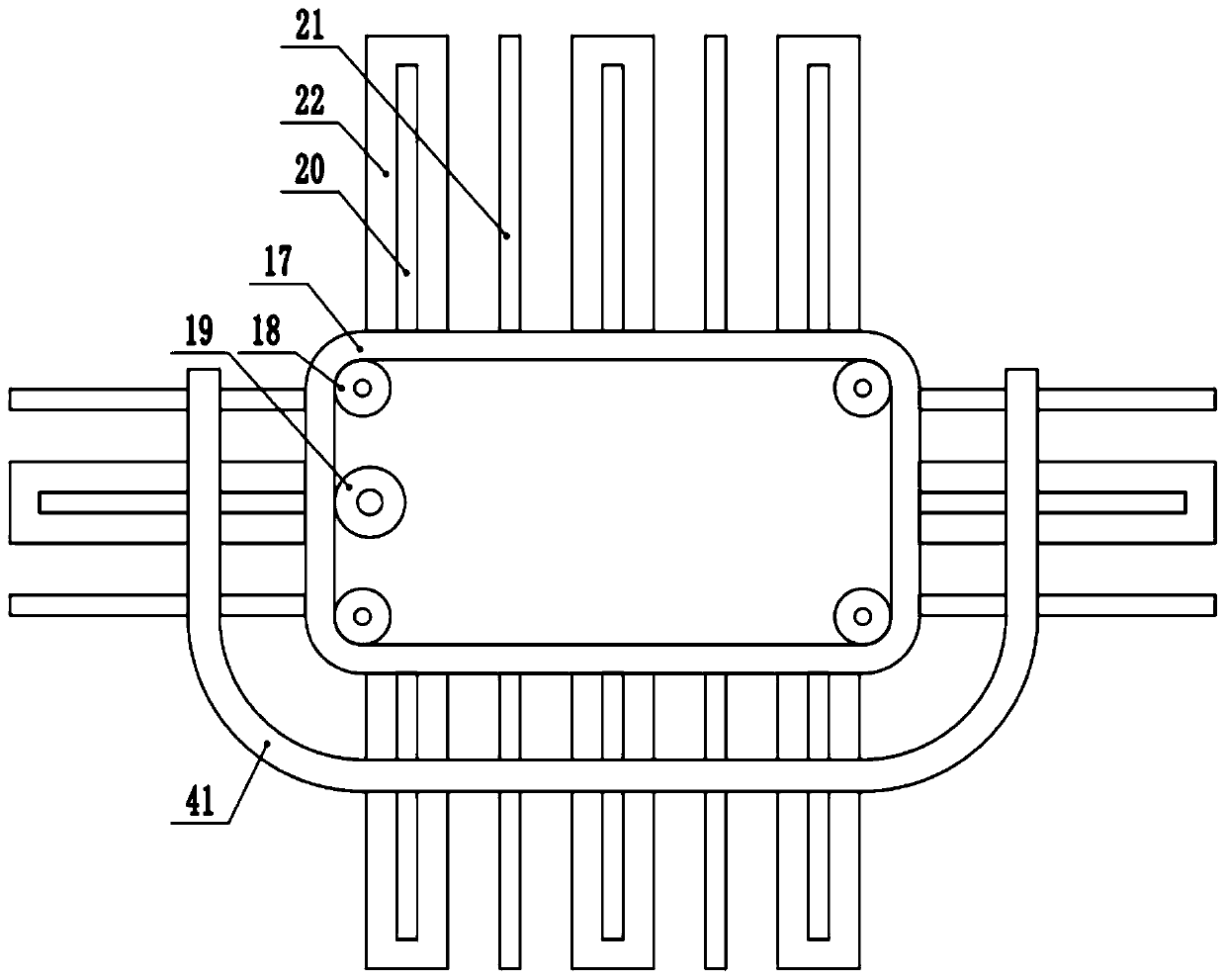
[0028] see Figure 1-7 , a kind of high-efficiency waste treatment equipment for mechanical production, comprising a treatment box 1, one end of the top of the treatment box 1 is fixedly connected to the feed hopper 2, the top end of the treatment box 1 is fixedly connected to the baffle 4, and the bottom of the baffle 4 is provided with a feeding Conveyor belt 3, feed conveyer belt 3 is driven by external drive equipment, the below of one end of feed conveyer belt 3 is provided with the second unloading cover 7, and one side of feed conveyer belt 3 is provided with adsorption separation device, the adsorption separation device The bottom is provided with a first blanking cover 6, and the bottom ends of the first blanking cover 6 and the second blanking cover 7 are respectively fixedly connected to the first forming output pipe 8 and the second forming output tube 9, the first forming output tube 8 and the second forming output pipe 9 are provided with a hybrid molding conveyi...

Embodiment 2

[0038] see Figure 1-7 , The other content of this embodiment is the same as that of Embodiment 1, except that: the bottom end of the dispersing frame 21 is fixedly provided with a plurality of dispersing claws 40 .

[0039]In the implementation process of the present invention, the metal debris produced by mechanical production is poured from the feed hopper 2, and then the external drive equipment is started to make the feed conveyor belt 3 run, and then the first drive motor 5 and the second drive motor 10 are started, The first drive motor 5 drives the drive gear 19 to rotate so that the transmission belt 17 drives the fixed rod 20, the dispersion frame 21 and the electromagnetic plate 22 to move. The ferrous material on the material conveyor belt 3 is absorbed until the fixed rod 20 breaks away from the conductive rail 41, the electromagnetic plate 22 loses its magnetism, and the ferrous material falls into the first blanking cover 6 below, and the non-ferrous material is...


PUM


Abstract

The invention discloses a garbage efficient disposal facility for mechanical production, and relates to the technical field of mechanical garbage disposal. The garbage efficient disposal facility formechanical production comprises a disposal box. A second blanking cover is arranged below one end of a feeding conveying belt, an absorption and separation device is arranged on one side of the feeding conveying belt, and a first blanking cover is arranged below the absorption and separation device. A first forming delivery pipe and a second forming delivery pipe are fixedly connected with the bottom ends of the first blanking cover and the second blanking cover correspondingly. Mixing forming conveying mechanisms are arranged inside the first forming delivery pipe and the second forming delivery pipe. A cutoff device is fixedly arranged outside the disposal box. According to the garbage efficient disposal facility for mechanical production, due to the fact that the absorption and separation device is arranged, iron-containing scraps in metal garbage can be absorbed, and separation and recovery are achieved; due to the fact that the mixing forming conveying devices, a gel conveying device and the cutoff device are arranged, the separated metal scrap garbage can be pressed and can be cut off to form block-shaped aggregations with the same size, transportation stacking and recovery statistics are facilitated, and the efficient and orderly disposal of the mechanical garbage is achieved.

Description

technical field [0001] The invention relates to the technical field of mechanical waste treatment, in particular to high-efficiency waste treatment equipment for mechanical production. Background technique [0002] With the rapid development of the economy, the machining industry is becoming more and more prosperous. Machining products are distributed in various production industries. During the machining process, more metal scraps and other garbage will be generated. If such garbage is directly filled Burial, because the decomposition of metal is slow, and the substances produced after metal decomposition will cause serious harm to the soil. In addition, direct landfill will prevent metal debris from being recycled, resulting in waste of resources. [0003] At present, the metal waste generated by mechanical processing is often treated by recycling, which has achieved the sustainable development of resources. However, the metal waste produced by machinery is often collected...

Claims


Application Information

Patent Timeline
IPC IPC(8): B30B11/24B30B15/08B30B15/30B03C1/18
CPCB03C1/18B30B11/24B30B15/08B30B15/302
Inventor 陈洪霖郑祥模
Owner 陈洪霖
Learn More