Metal diaphragm slotting loading circular waveguide circular polarizer

A metal diaphragm, circular polarizer technology, applied in waveguide devices, electrical components, circuits, etc., can solve problems such as easy generation of high-order modes, large phase fluctuations, and complex structures

Pending Publication Date: 2020-07-07
CHENGDU GLOBAL WAY COMM TECH
View PDF0 Cites 2 Cited by
  • Summary
  • Abstract
  • Description
  • Claims
  • Application Information

AI Technical Summary

Problems solved by technology

The circular polarizer is an important part of the circularly polarized antenna feeder system, and its performance determines the performance of the circularly polarized antenna. The traditional circular polarizer is in the form of symmetrical slots on the waveguide wall, or in the waveguide A dielectric diaphragm or a metal diaphragm is inserted into the cavity; the circular polarizer transforms the input linearly polarized wave into two polarization components with equal amplitudes and a phase difference of 90° between perpendicular and orthogonal phases through polarization rotation. The phase difference of each component determines the axial ratio of the circularly polarized antenna. The closer to 90°, the better the axial ratio of the antenna. When the traditional circular polarizer works in Ka and K frequency bands, the phase difference is basically 90°± At about 4°, the circular polarizer loaded with a dielectric diaphragm often uses screws to fix the dielectric diaphragm, which is prone to high-order modes; the traditional circular polarizer equipped with a dielectric diaphragm has a fixed size of the dielectric diaphragm, and electromagnetic waves of different frequencies After passing through the medium, it will be dispersed, and the influence of the dielectric diaphragm on the phase is different at different frequencies, resulting in uneven overall phase, and large fluctuations in the phase in the frequency band used; the circular polarizer of the traditional metal diaphragm is mostly in the form of a spacer. The structure is complex, the machining accuracy is high, the adjustability is poor, and high-order modes are easy to appear at high-end frequencies, resulting in resonance

Method used


Image

  • Metal diaphragm slotting loading circular waveguide circular polarizer
  • Metal diaphragm slotting loading circular waveguide circular polarizer

Examples


Embodiment Construction

[0009] The present invention will be further described below in conjunction with accompanying drawing:

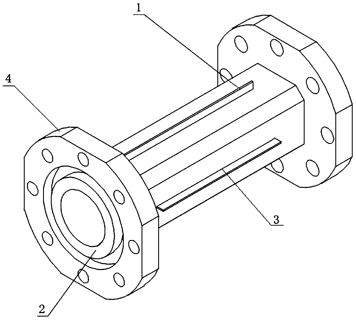
[0010] like figure 1 As shown, the metal diaphragm of the present invention is slotted to load a circular waveguide circular polarizer, including a metal diaphragm 1 and a circular waveguide 2; a metal diaphragm slot 3 is opened on the outer side of the circular waveguide 2; the metal diaphragm 1 is A stepped metal diaphragm 1 is inserted into the metal diaphragm slot 3 .

[0011] Specifically, the metal diaphragm slots 3 are symmetrically distributed outside the circular waveguide 2 .

[0012] Specifically, the metal diaphragm slots 3 are two groups of symmetrically distributed slots respectively arranged in the two polarization directions of the circular waveguide 2 .

[0013] Specifically, flanges 4 are provided at both ends of the circular waveguide 2 .

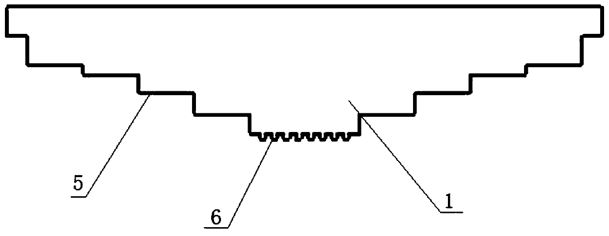
[0014] Specifically, the metal diaphragm 1 includes at least two steps 5 , and groove structures 6 are arranged o...


PUM


Abstract

The invention discloses a metal diaphragm slotting loading circular waveguide circular polarizer, and the polarizer comprises a metal diaphragm and a circular waveguide. A metal diaphragm slot is formed in the outer side of the circular waveguide; the metal diaphragm is a stepped metal diaphragm, and the metal diaphragm is inserted into the metal diaphragm slot. According to the invention, the phase difference of the circular polarizer in a wide frequency band can be kept near 90 degrees; the circular waveguide is slotted and loaded with the metal diaphragm, so a high-order mode can be greatlyinhibited, and high-order resonance is avoided; phase adjustment is achieved by adjusting the depth of the metal diaphragm inserted into the circular waveguide, adjustability is good, the structure is simple, the requirement for machining precision is lowered, and machining batch production is easy.

Description

technical field [0001] The invention belongs to the technical field of microwave communication, and in particular relates to a circular polarizer loaded with a circular waveguide loaded with slots on a metal diaphragm. Background technique [0002] With the rapid development of aerospace technology and electronic technology, the satellite communication industry has also developed rapidly. Satellite communication has become one of the main methods across oceans, continents, and countries, and has been widely used in both military and civilian applications. At present, there are more than 200 communication satellites in orbit on geostationary satellites. Most of these satellites use the C (6 / 4GHz) and Ku (14 / 12GHz) frequency bands, but the demand for satellite communication channel capacity continues to increase. The above two frequency bands Satellite communication systems in China are becoming increasingly crowded and cannot meet the current satellite broadband communication...

Claims


Application Information

Patent Timeline
IPC IPC(8): H01P1/17H01Q15/24
CPCH01P1/17H01Q15/244
Inventor 骆云于宏健温黔伟罗顺华呼延江利曹亮
Owner CHENGDU GLOBAL WAY COMM TECH
Why Eureka
Try Eureka