
Planar coil diaphragm loudspeaker and application thereof

A planar coil and speaker technology, applied in the field of electro-acoustics, can solve the problems of inability to transfer coils, increase in product cost, and insufficient low-frequency sound.

Inactive Publication Date: 2020-07-07
颜君玲
View PDF4 Cites 1 Cited by
  • Summary
  • Abstract
  • Description
  • Claims
  • Application Information

AI Technical Summary

Problems solved by technology

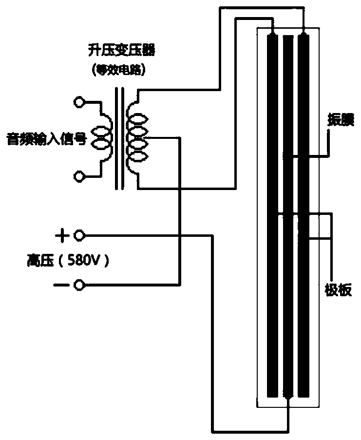
But the disadvantage is: because the driving force is inversely proportional to the square of the distance from the film to the pole plate, the electrostatic force F=ε*S*(U 2 / d 2 ), εdielectric constant, S film area, signal voltage between U film and plate, d is the distance between film and plate, electrostatic force is proportional to the square of the signal voltage, and proportional to the square of the distance from the film to the plate Inversely proportional, so the low-frequency sound is insufficient; the alternating audio signal must be boosted to several hundred volts to produce a sound acceptable to consumers. The boost process of broadband, low distortion, and high boost ratio greatly increases the cost of the product, which is why it is used The reason why the speakers and earphones of electrostatic speakers cost tens of thousands of yuan, or hundreds of thousands of yuan
[0017] To sum up, the existing technical solutions of planar coil speakers, whether it is a helical coil solution or a serpentine coil solution, the coil must be a closed curve, or a curve, or a helix connected in series from the end to the end. A closed line group always has a "starting end" and a "termination end"; and because the coil is usually a conductor, any two coils cannot be connected, which causes one of the two ends to be inside the closed coil, and the other end The point is outside the closed coil; the terminal located outside the closed coil is very easy to connect with the external circuit, such as a PCB pad, but how to export the terminal located inside the closed coil and connect it with the external circuit faces great challenges
From the above analysis, the current spot welding scheme, the scheme of perforating the middle of the membrane and connecting the coil ends on the upper and lower surfaces of the membrane through conductive glue, and the scheme of coil wires in a serpentine shape all have their own shortcomings.

Method used


Image

  • Planar coil diaphragm loudspeaker and application thereof
  • Planar coil diaphragm loudspeaker and application thereof
  • Planar coil diaphragm loudspeaker and application thereof

Examples


Embodiment 1

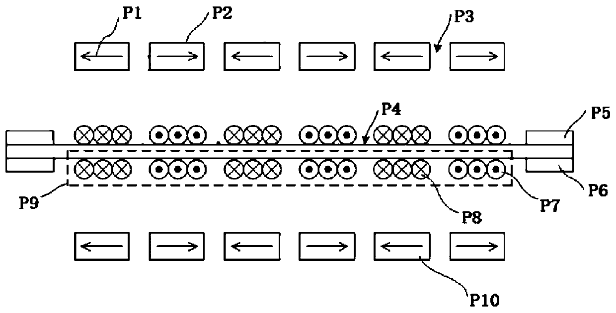
[0091] Such as Figure 7 , Figure 9 , Figure 10 and Figure 11 As shown, a planar coil diaphragm speaker includes a diaphragm assembly 5, the diaphragm assembly 5 includes a diaphragm 5a, the upper surface and the lower surface of the diaphragm 5a are respectively attached with a front coil 5d and a reverse coil 5g, and the front coil 5d and the reverse coil 5g is arranged mirror-symmetrically with the central plane of the vibrating membrane 5a as the plane of symmetry.

[0092] The routing mode of the front coil 5d and the rear coil 5g is spiral routing.

[0093] The two ends of the front coil 5d are respectively provided with a first end point 5e and a second end point 5f, the second end point 5f is located outside the front coil 5d, and the first end point 5e is located inside the front coil 5d; the two ends of the back coil 5g The ends are respectively provided with a third end point 5h and a fourth end point 5j, the fourth end point 5j is located outside the reverse...

Embodiment 2

[0120] The same part as that of Embodiment 1 has been discussed in detail in Embodiment 1, and will not be repeated here. Compared with Embodiment 1, this embodiment is modified as follows:

[0121] Such as Figure 17-Figure 19 As shown, the membrane assembly 5 includes a ring diaphragm 15, the diaphragm 15 replaces the diaphragm 5a, the center of the diaphragm 15 is provided with an inner ring 5m, and the outer edge is provided with an outer ring 5k, compared with the completely flat diaphragm 5a, adding two rings can increase the compliance of the diaphragm to vibrate up and down, that is, the diaphragm is easier to vibrate up and down.

[0122] In order to increase the rigidity of the membrane inner ring 5m and the membrane outer ring 5k, patterns can also be provided on the two rings, and the two rings and the patterns on the rings can be formed by hot pressing.

[0123] A front coil 5d and a back coil 5g are respectively attached to the upper surface and the lower surfac...

Embodiment 3

[0132] The same part as that of Embodiment 1 has been discussed in detail in Embodiment 1, and will not be repeated here. Compared with Embodiment 1, this embodiment is modified as follows:

[0133] Such as Figure 20 and 21As shown, the magnet assembly includes an upper vertically magnetized outer magnetic ring 13b, an upper vertically magnetized inner magnetic ring 14b, a lower vertically magnetized outer magnetic ring 13 and a lower vertically magnetized inner magnetic ring 14. The outer magnetic ring 13b for magnetization and the inner magnetic ring 14b for upper vertical magnetization are located above the diaphragm, the outer magnetic ring 13 for lower vertical magnetization and the inner magnetic ring 14 for lower vertical magnetization are located below the diaphragm, and the upper vertical magnetization inner magnetic ring 14 is located below the diaphragm. The magnetic outer magnetic ring 13b and the upper vertically magnetized inner magnetic ring 14b are fixed on t...


PUM


Abstract

The invention discloses a planar coil diaphragm loudspeaker, which comprises an outer shell, wherein a membrane assembly, a magnet assembly and a supporting assembly are packaged in the outer shell; the membrane assembly at least comprises a coil, the two ends of the coil are each provided with an end point, one end point is located in the coil, and the other end point is located outside the coil;the number of the supporting assemblies is at least one; the supporting assemblies are used for supporting the membrane assembly; the surfaces, making contact with the membrane assembly, of the supporting assemblies are provided with bonding pads connected with end points located outside the coil; and the supporting assemblies are further provided with bonding pads for audio current input and bonding pads for audio current output. Compared with the prior art, the planar coil diaphragm loudspeaker has the advantages that the problem of how to effectively connect the internal end point of the closed coil with the outside is solved, the integrity of the membrane is not damaged, the area of the membrane is utilized to the maximum extent, damage to the film caused by spot welding or conductiveadhesive bonding after perforation is avoided, and damage to the integrity of the film is further avoided.

Description

technical field [0001] The invention relates to a planar coil diaphragm loudspeaker and its application, belonging to the technical field of electroacoustics. Background technique [0002] Loudspeaker, commonly known as "horn", is an electroacoustic transducer and is widely used in speakers, earphones, mobile phones, wearable devices, robots, home appliances and other devices or facilities that need to emit sound. Current speakers include dynamic speakers, electrostatic speakers and planar coil diaphragm speakers in terms of working principles. [0003] The dynamic speaker is the most widely used speaker because of its simple structure, mature technology and good performance. However, the disadvantage of the dynamic speaker is that the transient characteristics are not good due to the large vibration mass such as the coil; The uniformity and the asymmetry of the BL electromagnetic driving force lead to different degrees of rocking vibration; because only the coil and the bo...

Claims


Application Information

Patent Timeline
IPC IPC(8): H04R7/06H04R9/02H04R9/04H04R9/06
CPCH04R7/06H04R9/025H04R9/04H04R9/06
Inventor 颜君玲
Owner 颜君玲
Learn More