Waste gas treatment equipment

A technology of waste gas treatment equipment and treatment chamber, which is applied in the direction of gas treatment, combined device, membrane technology, etc., which can solve the problems of environmental pollution and toxicity, etc., and achieve the effect of simple equipment, convenient operation and high purification efficiency

Inactive Publication Date: 2020-07-10
铭牌精工机械(山东)有限公司
View PDF6 Cites 1 Cited by
  • Summary
  • Abstract
  • Description
  • Claims
  • Application Information

AI Technical Summary

Problems solved by technology

These organic solvents are mainly low-boiling point, volatile organic compounds with certain toxicity, and a considerable part of them are finally discharged into the atmosphere in the form of organic waste gas, causing serious pollution to the surrounding environment

Method used


Image

  • Waste gas treatment equipment
  • Waste gas treatment equipment

Examples


Embodiment 1

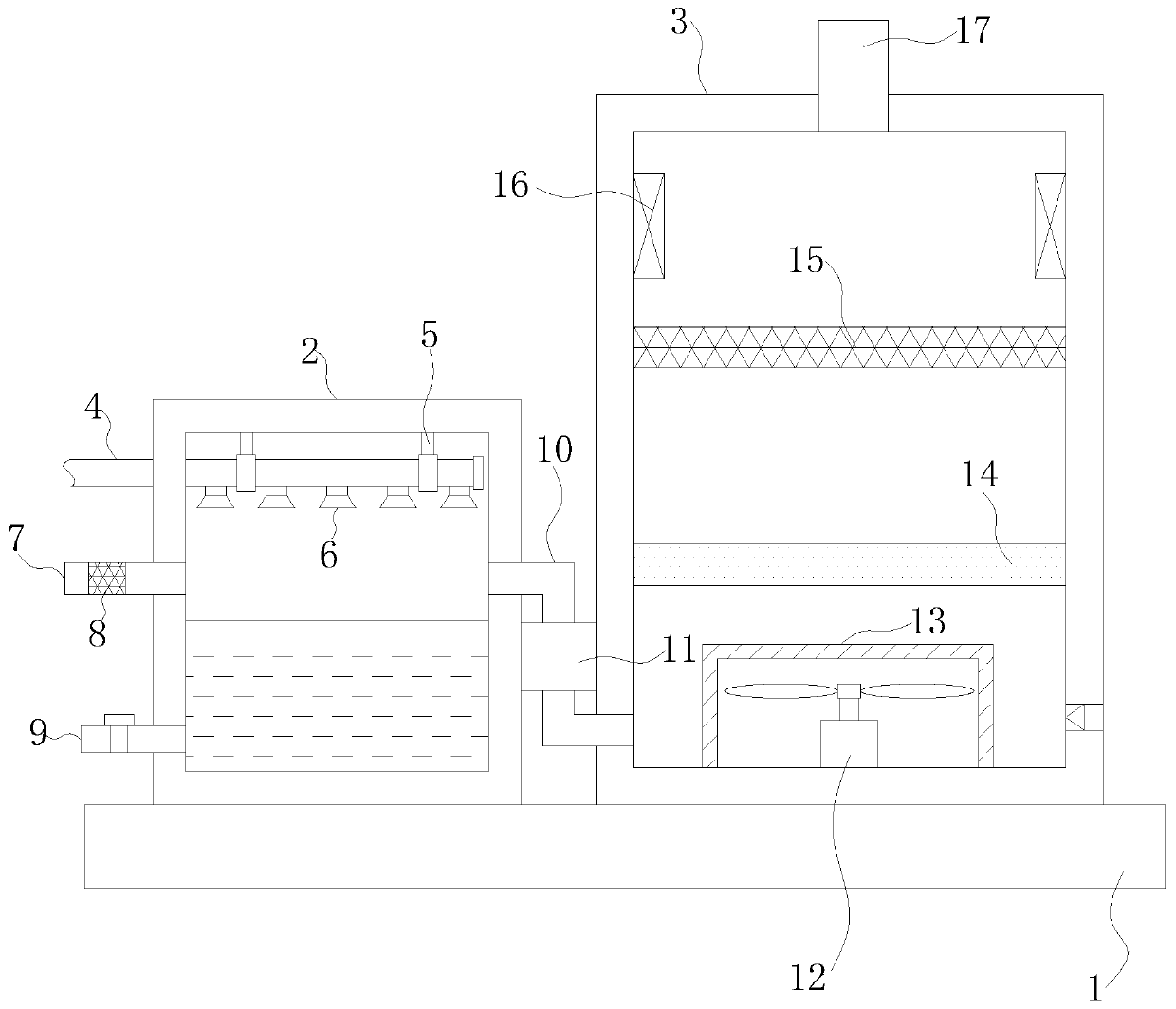
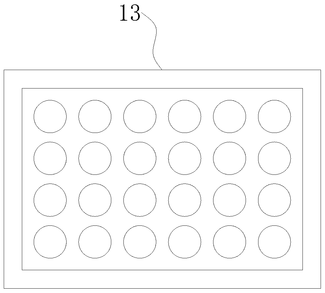
[0017] Such as Figure 1-2 As shown, the present invention provides a kind of technical scheme:

[0018] A kind of exhaust gas treatment equipment, comprising a bottom plate 1, a humidification chamber 2 is fixedly connected to the top left side of the bottom plate 1, a water storage tank is arranged inside the humidification chamber 2, and a water outlet pipe 9 is arranged on the left side of the bottom of the humidification chamber 2, and the water outlet pipe 9 is connected to The water storage tank is connected, the outside of the outlet pipe 9 is provided with a switch valve 1, the right side of the top of the bottom plate 1 is fixedly connected to the treatment chamber 3, and the lower right corner of the treatment chamber 3 is provided with a one-way air hole, and the top of the bottom plate 1 is provided with the water inlet pipe 4, the water inlet pipe 4 It runs through the humidification chamber 2 and extends to the interior of the humidification chamber 2. The outer...

Embodiment 2

[0029] Such as Figure 1-2 As shown, the present invention provides a kind of technical scheme:

[0030] A kind of exhaust gas treatment equipment, comprising a bottom plate 1, a humidification chamber 2 is fixedly connected to the top left side of the bottom plate 1, a water storage tank is arranged inside the humidification chamber 2, and a water outlet pipe 9 is arranged on the left side of the bottom of the humidification chamber 2, and the water outlet pipe 9 is connected to The water storage tank is connected, the outside of the outlet pipe 9 is provided with a switch valve 1, the right side of the top of the bottom plate 1 is fixedly connected to the treatment chamber 3, and the lower right corner of the treatment chamber 3 is provided with a one-way air hole, and the top of the bottom plate 1 is provided with the water inlet pipe 4, the water inlet pipe 4 It runs through the humidification chamber 2 and extends to the interior of the humidification chamber 2. The outer...

Embodiment 3

[0040] Such as Figure 1-2 As shown, the present invention provides a kind of technical scheme:

[0041] A kind of exhaust gas treatment equipment, comprising a bottom plate 1, a humidification chamber 2 is fixedly connected to the top left side of the bottom plate 1, a water storage tank is arranged inside the humidification chamber 2, and a water outlet pipe 9 is arranged on the left side of the bottom of the humidification chamber 2, and the water outlet pipe 9 is connected to The water storage tank is connected, the outside of the outlet pipe 9 is provided with a switch valve 1, the right side of the top of the bottom plate 1 is fixedly connected to the treatment chamber 3, and the lower right corner of the treatment chamber 3 is provided with a one-way air hole, and the top of the bottom plate 1 is provided with the water inlet pipe 4, the water inlet pipe 4 It runs through the humidification chamber 2 and extends to the interior of the humidification chamber 2. The outer...


PUM


Abstract

The invention relates to the technical field of waste gas treatment, and discloses waste gas treatment equipment. The equipment comprises a bottom plate, a humidifying chamber is fixedly connected tothe left side of the top of the bottom plate, a treatment chamber is fixedly connected to the right side of the top of the bottom plate, a water inlet pipe is arranged at the top of the bottom plate,penetrates through the humidifying chamber and extends into the humidifying chamber, supports are fixedly connected to the outer surfaces of the two ends of the humidifying chamber, and the tops of the two supports are fixedly connected with the humidifying chamber. According to the invention, waste gas is sprayed; the waste gas is preliminarily filtered by the filter material plate, harmful organic matters in the waste gas and a catalyst fixed on the filter material plate are decomposed under the catalytic action, residual particles in the waste gas are adsorbed by a filter screen II, and finally, the waste gas is purified and sterilized by the ultraviolet lamp, so that the purpose of purifying the waste gas is achieved, and the equipment is simple, convenient to operate and good in removal effect.

Description

technical field [0001] The invention relates to the technical field of waste gas treatment, in particular to waste gas treatment equipment. Background technique [0002] At present, a large amount of organic solvents are generally used in printing, spraying and other industries, such as benzene, toluene, xylene and other aromatic solvents and ethanol, isopropanol, ethyl acetate, butyl acetate, butanone, dichloroethane , ethyl chloride, hydrocarbons, etc. These organic solvents are mainly low-boiling point, volatile organic compounds with certain toxicity, and a considerable part of them are finally discharged into the atmosphere in the form of organic waste gas, causing serious pollution to the surrounding environment. Therefore, in the context of the current severe environmental protection situation and the country's increasing investment in environmental protection year by year, recycling and reusing organic components in exhaust gas through appropriate methods can not on...

Claims


Application Information

Patent Timeline
Patent Type & Authority Applications(China)
IPC IPC(8): B01D53/75B01D53/74B01D53/86B01D53/00B01D50/00
CPCB01D53/75B01D53/74B01D53/86B01D53/007B01D2259/804B01D50/60
Inventor 张书生
Owner 铭牌精工机械(山东)有限公司
Why Eureka
Try Eureka