
Waste gas treatment device employing coupling of ultraviolet catalytic oxidation and double-layer bio-trickling filter

An exhaust gas treatment device, catalytic oxidation technology, applied in the direction of gas treatment, chemical/physical process, catalyst activation/preparation, etc., can solve the problems of clogged void channels, low operating costs, large processing capacity, etc. Reasonable fluid bed distribution and the effect of improving treatment efficiency

Pending Publication Date: 2021-09-17
SHANGHAI SECOND POLYTECHNIC UNIVERSITY
View PDF9 Cites 0 Cited by
  • Summary
  • Abstract
  • Description
  • Claims
  • Application Information

AI Technical Summary

Problems solved by technology

[0005] Photocatalytic oxidation technology has mild reaction conditions, low energy consumption, simple operation, and can be carried out at normal temperature and pressure. The reaction does not require complicated conditions, but photocatalytic oxidation technology has problems such as short life, electrode aging, and maintenance.
The biological trickling filtration method has the advantages of no pollution, low energy consumption, large processing capacity, and low operating costs, but there are problems such as insufficient microbial activity and excessive growth of bacteria to block the gap channels.

Method used


Image

  • Waste gas treatment device employing coupling of ultraviolet catalytic oxidation and double-layer bio-trickling filter
  • Waste gas treatment device employing coupling of ultraviolet catalytic oxidation and double-layer bio-trickling filter
  • Waste gas treatment device employing coupling of ultraviolet catalytic oxidation and double-layer bio-trickling filter

Examples


Embodiment 1

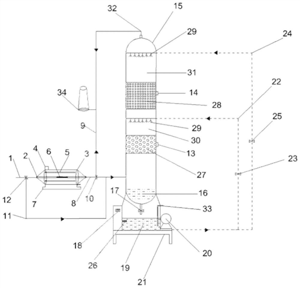
[0037] see figure 1 As shown, the present invention provides a waste gas treatment device for combined use of ultraviolet photocatalytic oxidation and double-layer bio-trickling filter tower, including an air intake pipe 1, a quartz catalytic oxidation pipe 2, a stainless steel cavity 3, a first electrical control box 4, a UV Ultraviolet lamp 5, MnOx / SiC composite photocatalyst 6, base 7, air intake pipeline 8, emergency exhaust pipeline 9, first emergency valve 10, emergency pipeline 11, second emergency valve 12, lower inspection port 13, upper inspection Port 14, double-layer trickling filter tower 15, circulating water layer 16, flow control valve 17, second electrical control box 18, nutrient solution storage tank 19, circulating pump 20, dripping filter tower base 21, lower circulating water pipe 22, lower electromagnetic Flow control valve 23, upper circulating water pipe 24, upper electromagnetic flow control valve 25, liquid level gauge 26, polyurethane biological bed...


PUM

PropertyMeasurementUnit
wavelengthaaaaaaaaaa
lengthaaaaaaaaaa
heightaaaaaaaaaa

Abstract

The invention discloses a waste gas treatment device employing coupling of ultraviolet catalytic oxidation and a double-layer bio-trickling filter. The waste gas treatment device comprises ultraviolet catalytic oxidation equipment and double-layer bio-trickling filtration equipment, wherein an UV lamp tube and a MnOx / SiC composite photocatalyst are arranged in the ultraviolet catalytic oxidation equipment; the double-layer bio-trickling filtration equipment comprises the double-layer bio-trickling filter; a polyurethane biological flow bed and a polyurethane biological bottom bed are arranged in the bio-trickling filter at an interval along a vertical direction; and atomizing nozzles are respectively arranged above the polyurethane biological bed at the upper layer and above the polyurethane biological bed at the lower layer, and the atomizing nozzles are connected with a nutrient solution storage tank. According to the invention, pollutants in waste gas are purified through photocatalytic oxidation based on the oxidation-reduction capability of the MnOx / SiC composite photocatalyst under an illumination condition; and meanwhile, trace ozone generated by photocatalytic oxidation enters the double-layer bio-trickling filtration equipment, so the waste gas purification efficiency of microorganisms can be further improved. The device is suitable for treatment of low-flow high-concentration waste gas.

Description

technical field [0001] The invention relates to the technical field of waste gas treatment, in particular to an ultraviolet photocatalytic oxidation coupled double-layer biological trickling filter tower waste gas treatment device. Background technique [0002] Air pollution is already a nightmare for human beings, and the pollutants are divided into particulate matter and gaseous matter, and gaseous matter is divided into inorganic pollutants and organic pollutants. Among them, organic pollutants account for the vast majority, and most of them are volatile organic compounds, referred to as VOCs. Therefore, VOCs purification treatment has become a hot spot in the world. [0003] At present, the main treatment methods of VOCs can be divided into physical methods, chemical methods and biological methods. Biological method is a low-pollution technology that can replace traditional physical and chemical methods to treat VOCs. It mainly oxidizes and decomposes organic waste gas...

Claims


Application Information

Patent Timeline
Patent Type & Authority Applications(China)
IPC IPC(8): B01D53/75B01D53/84B01D53/86B01D53/44B01D53/72B01J27/224B01J35/00B01J37/03
CPCB01D53/007B01D53/75B01D53/84B01D53/864B01D53/8687B01J27/224B01J37/035B01D2257/7027B01D2257/708B01D2251/104B01D2259/804B01J35/391B01J35/39Y02A50/20
Inventor 关杰周铜戴珏袁昊郭耀广刘昶翟旭峰阮琪文
Owner SHANGHAI SECOND POLYTECHNIC UNIVERSITY
Learn More