
Long-pin bent plate chain

A bending plate chain and bending chain technology, applied in the field of transmission chain, can solve the problems of large fluctuation of working conditions, unsuitable chain, large carbon content in slag, etc. big effect

Pending Publication Date: 2020-07-10
安徽黄山中友链条制造有限公司
View PDF0 Cites 0 Cited by
  • Summary
  • Abstract
  • Description
  • Claims
  • Application Information

AI Technical Summary

Problems solved by technology

[0007] Aiming at the deficiencies of the prior art, the present invention provides a long-pin bent plate chain, which overcomes the deficiencies of the prior art, has a reasonable design and a compact structure, and aims to solve the problem of high furnace temperature and slag Large carbon content, high boiler efficiency, and large fluctuations in the working environment, the problem that the traditional chain cannot be applied

Method used


Image

  • Long-pin bent plate chain
  • Long-pin bent plate chain
  • Long-pin bent plate chain

Examples


Embodiment 1

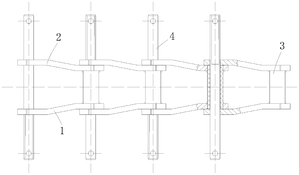
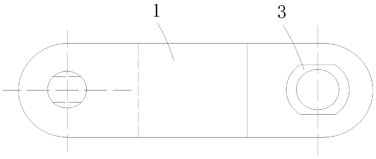
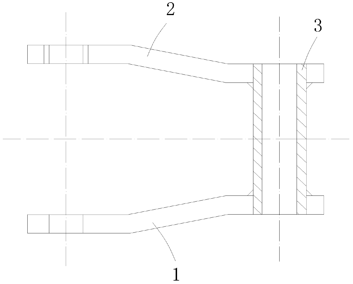
[0035] A long pin bent plate chain, comprising a set of series-connected chain links, each of the chain links includes a round hole bent link plate 1, a flat hole bent link plate 2, a sleeve 3 and a long pin shaft 4;

[0036] In this embodiment, such as Figure 1-3 As shown, the round hole bent chain plate 1 and the flat hole bent chain plate 2 are plate bodies of the same specification, and the round hole bent chain plate 1 and the flat hole bent chain plate 2 are symmetrically arranged. The plate body of the hole-bending chain plate 2 is bent outwards on the same side, and the end of the bending portion is provided with an outer sleeve portion arranged parallel to the plate body, and the outer sleeve portion of the round hole curved chain plate 1 A round pin hole 101 is opened in the middle, and a flat pin hole 201 is opened in the middle of the outer sleeve part of the flat-hole bent chain plate 2;

[0037] The round hole curved chain plate 1 and the flat hole curved chain plate...

Embodiment 2

[0046] The difference between this embodiment and embodiment 1 lies in figure 1 , 4 As shown in -6, the side wall of one end of the long pin shaft 4 is integrally formed with a flat end 401 that is symmetrically recessed inward, and the flat end 401 is matched and inserted into the flat pin hole 201, and the flat end 401 prevents the pin from rotating The role of.

[0047] In this embodiment, such as Figure 6-7 As shown, the flat surface of the flat end 401 is cut inward to 1 / 5-1 / 4 of the cross-sectional radius of the long pin shaft 4, and the long pin shaft 4 passes through the link frame to connect the chain. The flat end 401 is cut into The depth limitation effectively prevents the rotation of the pin shaft.

[0048] Refer to Embodiment 1 for other undescribed structures.

[0049] According to the long-pin bent plate chain of the above-mentioned embodiment of the present invention, the round hole bent link plate 1 and the flat hole bent link plate 2 are connected in a staggered...


PUM


Abstract

The invention relates to the technical field of transmission chains, provides a long-pin bent plate chain, and solves the problems of high furnace temperature, high carbon content of slag, high steamboiler efficiency, high working condition environment fluctuation and incapability of applying a traditional chain in a novel chain wheel and chain transmission boiler. The long-pin bent plate chain comprises a set of serially connected chain links, wherein each chain link includes a circular hole bent plate, a flat hole bent plate, a sleeve and a long pin shaft; the circular hole bent plate and the flat hole bent plate are plate bodies with the same specification, and are symmetrically arranged; bent parts are outwards bent on the same sides of the plate bodies of the circular hole bent plateand the flat hole bent plate; outer edge sleeving parts parallel to the plate bodies are arranged at the tail ends of the bent parts; circular pin holes are formed in the middle parts of the outer edge sleeving parts of the circular hole bent plate; and flat pin holes are formed in the middle parts of the outer edge sleeving parts of the flat hole bent plate. The long-pin bent plate chain is particularly suitable for working condition environments of the novel chain wheel and chain transmission boiler, and is higher in social use value and application prospect.

Description

Technical field [0001] The invention relates to the technical field of transmission chains, in particular to a long-pin bent plate chain. Background technique [0002] Chain is a kind of mechanical product with strong versatility. Because it has the characteristics of gear and belt, it has been widely used in transmission, conveying and some special occasions. [0003] The curved plate chain is a special chain for strong impact and abrasive conveying. It has high strength, small flexibility, compact structure, not easy to deform, low friction, and can be conveyed at high speed, horizontal and inclined, and can also be connected with peripheral equipment. Do continuous operation or controlled operation, easy to maintain, stable and reliable operation. [0004] The curved plate chain conveyor equipment can withstand large loads and long-distance transportation; the line body is linear and curved transportation. With the continuous development of automated production, the mechanization...

Claims


Application Information

Patent Timeline
IPC IPC(8): B65G17/40
CPCB65G17/40
Inventor 戴兴仁叶玲汪秋萍
Owner 安徽黄山中友链条制造有限公司
Learn More