
Pump split type crosshead

A crosshead, split-type technology, applied to pump components, variable capacity pump components, liquid fuel engines, etc., can solve the problems of crosshead cavity demoulding difficulties, reduce material utilization, increase machining hours, etc., to achieve The effect of reducing maintenance costs, reducing costs, and improving production efficiency

Pending Publication Date: 2020-07-10
上海清力源流体科技有限公司
View PDF0 Cites 0 Cited by
  • Summary
  • Abstract
  • Description
  • Claims
  • Application Information

AI Technical Summary

Problems solved by technology

[0004] With the increase of the service life, the wear of the side wall of the inner cavity of the crosshead is increasing, but under the lubricating effect of the oil seal, the wear of the extension area of ​​the crosshead is much smaller than that of the inner cavity of the crosshead, but once the wear of the crosshead exceeds a certain level, Then the crosshead needs to be replaced as a whole, and the follow-up maintenance cost is relatively high
[0005] In addition, if plastic forming is adopted, that is, the forging method will bring the following problems: it is difficult to demould the inner cavity of the crosshead, and the oil hole and pin hole in the inner cavity need post-processing, which reduces the utilization rate of materials and increases the machine tool. The working hours of processing; if the liquid forming method is adopted, although a series of problems caused by forging can be avoided, but due to the limitations of the casting itself for the crosshead with strict working conditions, the casting material The grains are often relatively coarse, and any small casting defects such as insufficient pouring, cold shut, slag inclusions, and pores are not allowed

Method used


Image

  • Pump split type crosshead
  • Pump split type crosshead
  • Pump split type crosshead

Examples


Embodiment Construction

[0022] In order to enable those skilled in the art to better understand the technical solutions of the present invention, the present invention will be further described in detail below in conjunction with the accompanying drawings and preferred embodiments.

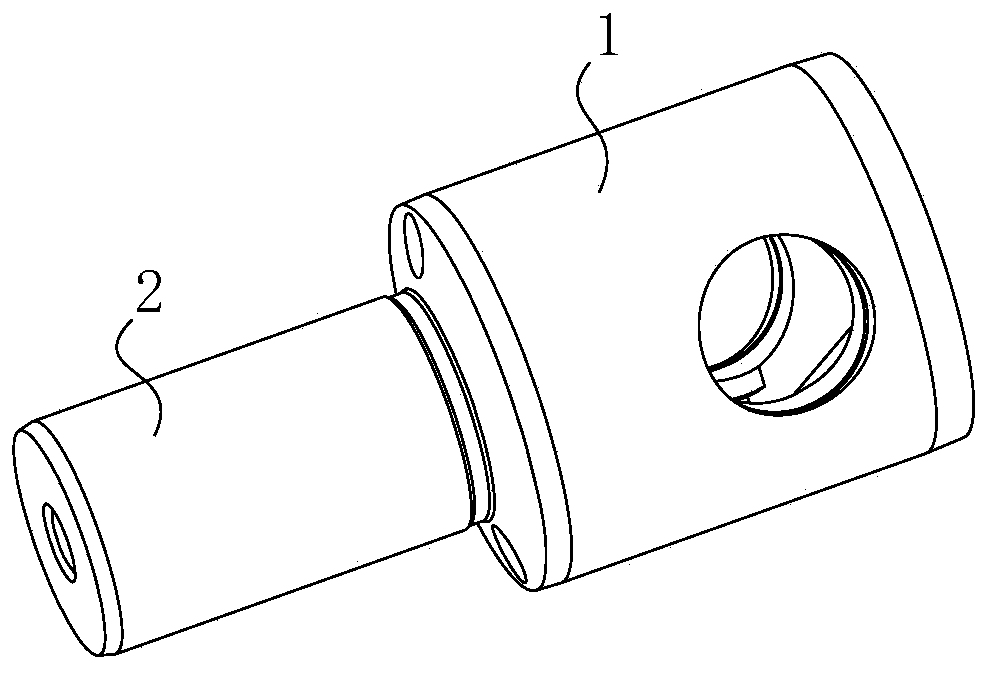
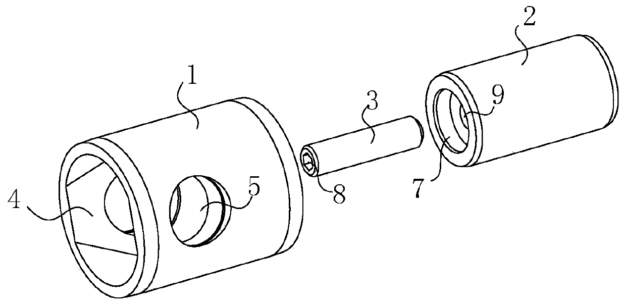
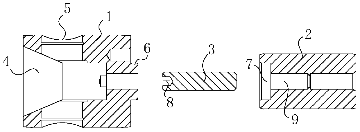
[0023] As shown in the figure, the present invention provides a split crosshead for pumps, which includes a split crosshead main body 1, crosshead extension 2 and locking parts 3, the crosshead main body 1 and crosshead extension 2 are cylindrical structure, and the diameter of the crosshead extension 2 is smaller than that of the crosshead main body 1. In the later actual use process, the wear degree of the crosshead extension 2 is much smaller than that of the crosshead main body 1, so the staff can only replace the crosshead main body 1, thereby reducing the later stage The maintenance cost is reduced to reduce the cost. The left side of the crosshead main body 1 is provided with an inner cavity 4 for inserting one end...


PUM


Abstract

The invention provides a pump split type crosshead and relates to the field of high-pressure plunger pump components. The pump split type crosshead comprises a split type crosshead main body, a crosshead stretcher and a locking component; during the later actual using process, the wear degree of the crosshead stretcher is far less than that of the crosshead main body, so that a working staff can change the crosshead main body only, the later maintaining cost is further reduced, and the cost is decreased; in addition, the crosshead main body and the crosshead stretcher can be separately manufactured, so that later treatment to the cavity and the pin hole of the crosshead is further avoided, and the production efficiency is improved; and moreover, the locking component can lock the crossheadmain body and the crosshead stretcher in the axial direction to prevent the connecting part of the crosshead main body and the crosshead stretcher from breaking, so that the overall strength of the crosshead can be effectively improved.

Description

technical field [0001] The invention relates to the field of high-pressure plunger pump components, in particular to a split type crosshead for pumps. Background technique [0002] The power end transmission mechanism of the existing high-pressure plunger pump mainly includes crankshaft, connecting rod and crosshead. The connecting rod at the power end and the ceramic plunger at the water end are connected through the crosshead. This method of avoiding the direct connection between the ceramic plunger and the connecting rod protects the ceramic plunger from the side pressure brought by the connecting rod, thereby protecting the brittle ceramic plunger. [0003] In the field of high-pressure plunger pumps, the crosshead is placed in the crankcase. In order to ensure the airtightness of the crankcase, it is usually necessary to nest an oil seal on the crosshead extension, so the length of the crosshead extension almost accounts for the overall length of the crosshead. One-hal...

Claims


Application Information

Patent Timeline
IPC IPC(8): F04B53/14F04B53/22
CPCF04B53/14F04B53/22
Inventor 周江明
Owner 上海清力源流体科技有限公司
Learn More