Fluid temperature field analysis method for double-pipe buried pipe heat exchanger

A buried tube heat exchanger and fluid temperature technology, applied in indirect heat exchangers, geothermal collectors, geothermal energy, etc., can solve the problem of ignoring the heat capacity of boreholes and the unsteady heat transfer of boreholes, and the calculation of three-dimensional numerical models complex process, etc.

Active Publication Date: 2020-07-10
ANHUI UNIVERSITY OF TECHNOLOGY
View PDF8 Cites 4 Cited by
  • Summary
  • Abstract
  • Description
  • Claims
  • Application Information

AI Technical Summary

Problems solved by technology

[0007]However, the above-mentioned first document ignores the non-uniform distribution of borehole heat capacity and fluid axial temperature, and the calculation process of the 3D numerical model in the second document is very complicated , while th

Method used


Image

  • Fluid temperature field analysis method for double-pipe buried pipe heat exchanger
  • Fluid temperature field analysis method for double-pipe buried pipe heat exchanger
  • Fluid temperature field analysis method for double-pipe buried pipe heat exchanger

Examples


Embodiment 1

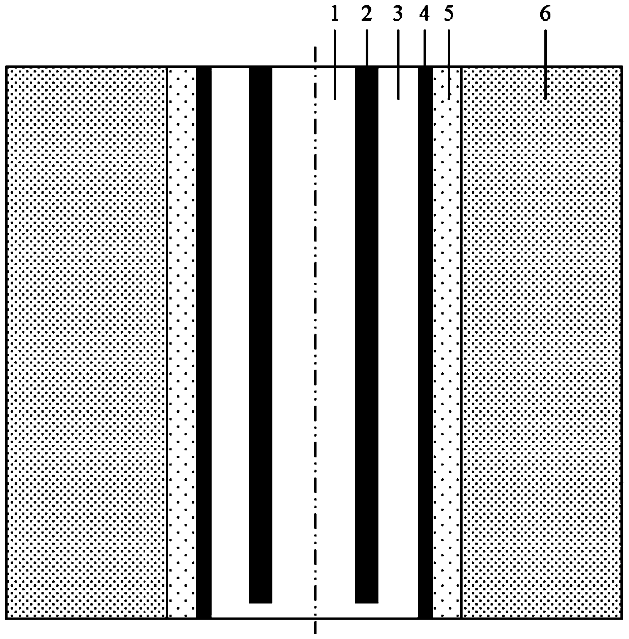
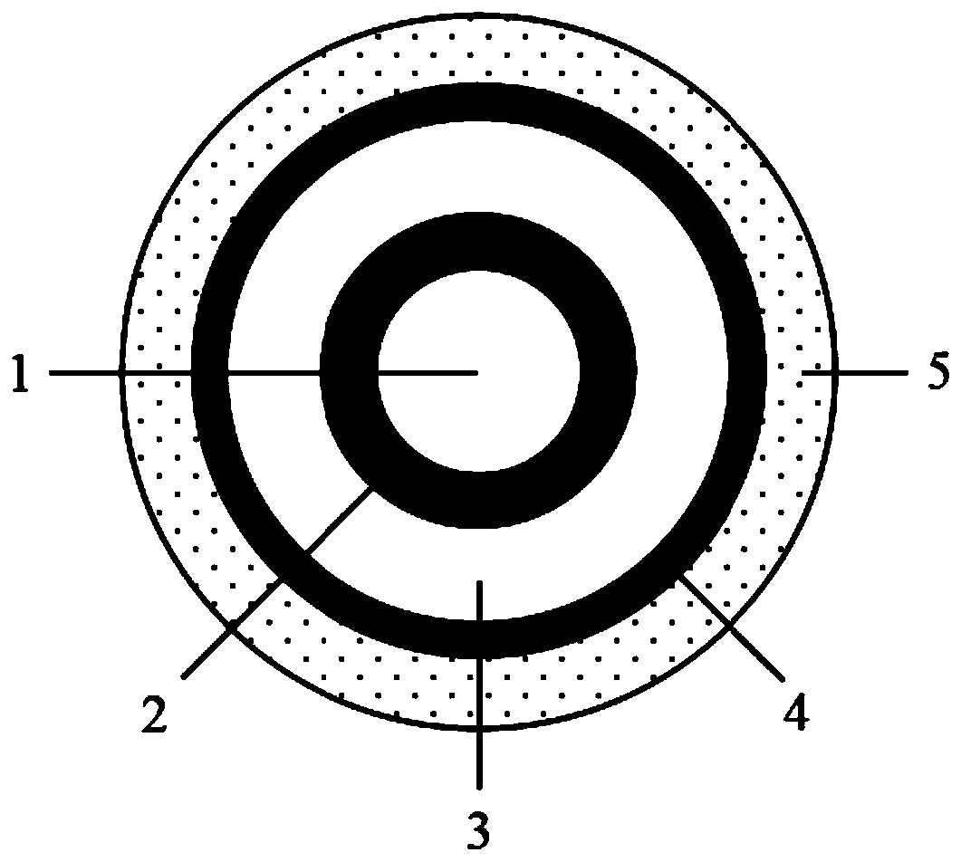
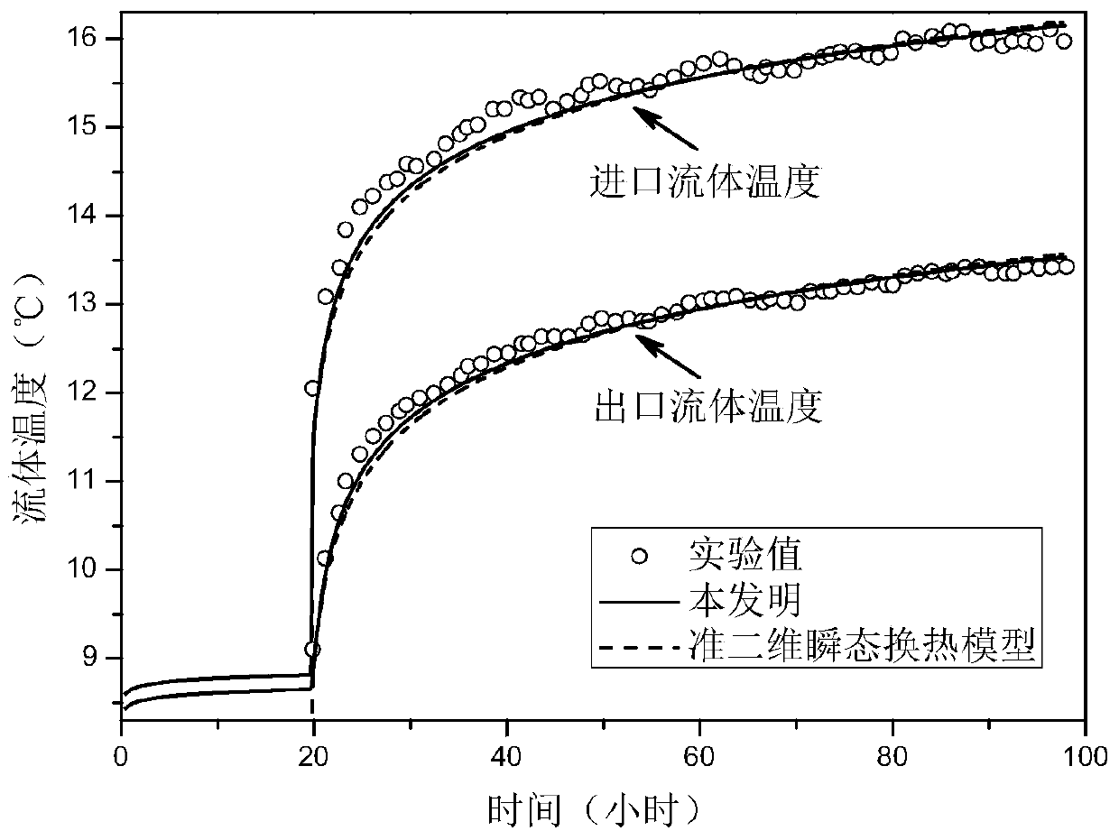
[0137] In this embodiment, the casing-type buried pipe heat exchanger is as follows: figure 1 and figure 2 As shown, the flow direction of the fluid is in and out, for the Swedish Royal Institute of Technology completed the thermal response test in 2009, calculated the fluid temperature field at different times, and compared the calculated values ​​with the experimental values ​​and the quasi-two-dimensional transient heat transfer model.

[0138] The total duration of the thermal response test is 97.9 hours, then the total simulation time t tol = 97.9 hours. The thermal response test includes two stages: the first 19.8 hours is the pre-circulation stage, and the heat exchange power is about 400W; the last 78.1 hours is the heat injection stage, and the heat exchange power is about 6360W. Set the time step Δt=1 minute, then the number of time segments N=t tol / Δt=5874.

[0139] Divide the inner pipe fluid 1 into 51 nodes along the axial direction, that is, M=51, and the...

Embodiment 2

[0146] In this embodiment, the casing-type buried pipe heat exchanger is as follows: figure 1 and figure 2 As shown, the flow direction of the fluid is outside in and inside out. For the deep casing type ground heat exchanger in the typical area of ​​northern my country, the fluid temperature field at different times is calculated, and the calculated value is compared with that of Kong Yanlong et al. based on OpenGeoSys software. Compared with simulated values.

[0147] The total duration of the OpenGeoSys simulation is 120 days, then the total simulation time t tol = 120 days. Set the time step Δt=30 minutes, then the number of time segments N=t tol / Δt=5760.

[0148] Divide the inner pipe fluid 1 into 51 nodes along the axial direction, that is, M=51, and the length of the heat exchanger L=2000m, then the axial coordinate z of the mth node m =(m-1)L / (M-1)=40(m-1). Similarly, the outer tube fluid 3 is equally divided into 51 nodes along the axial direction.

[0149] At...


PUM


Abstract

The invention discloses a fluid temperature field analysis method for a double-pipe buried pipe heat exchanger, and belongs to the technical field of ground source heat pumps. The method comprises thesteps: establishing transient heat transfer equations of an inner pipe fluid and an outer pipe fluid, analyzing radial one-dimensional heat transfer in backfill soil and soil by adopting a compositemedium column heat source model, and respectively establishing a heat transfer model of the double-pipe buried pipe heat exchanger in two flowing directions (inner-in and outer-out: the fluid flows infrom the inner pipe and flows out from the outer pipe; wherein a fluid flows in from the outer pipe and flows out from the inner pipe); based on the established heat transfer model, setting a time step length, equally dividing an inner pipe fluid and an outer pipe fluid into a plurality of nodes along the axial direction respectively, dispersing a heat transfer equation, establishing an algebraicequation of each node, and calculating the temperatures of all nodes at each moment by adopting an iterative method, thereby completing the calculation of fluid temperature fields changing along withdepth and time in two flowing directions. The method has the characteristics of small calculation amount, high precision, wide applicability and the like.

Description

technical field [0001] The invention belongs to the technical field of ground source heat pumps, and more specifically relates to a method for analyzing the fluid temperature field of a casing-type ground-buried heat exchanger. Background technique [0002] The casing type buried tube heat exchanger is a common buried tube heat exchanger in the ground source heat pump system, and has a great application prospect in the utilization of medium and deep geothermal energy. The analysis method of fluid temperature field in heat exchanger is the theoretical basis of thermal response test and design of buried pipe heat exchanger, so it is an important research content. At present, the heat transfer models for analyzing the fluid temperature field of heat exchangers mainly include traditional analysis models (including line heat source analysis models, column heat source analysis models, etc.), segmented finite line heat source analysis models, quasi-two-dimensional transient heat tr...

Claims


Application Information

Patent Timeline
IPC IPC(8): G06F30/20G06F119/08F28D15/06F24T10/13
CPCF28D15/06F24T10/13Y02E10/10F24T2201/00
Inventor 王昌龙鲁月红黄志甲方晗陈乐文
Owner ANHUI UNIVERSITY OF TECHNOLOGY
Why Eureka
Try Eureka