Maximum torque current ratio control method for built-in permanent magnet synchronous motor

A technology of permanent magnet synchronous motor and maximum torque current, which is applied in motor control, motor generator control, AC motor control, etc., and can solve problems such as inaccurate derivative information and difficulty in obtaining maximum torque current

Active Publication Date: 2020-07-10
TIANJIN UNIV
View PDF6 Cites 6 Cited by
  • Summary
  • Abstract
  • Description
  • Claims
  • Application Information

AI Technical Summary

Problems solved by technology

However, since the torque is a trigonometric function of the current angle, the remaining part is considered to be the derivative informati...

Method used


Image

  • Maximum torque current ratio control method for built-in permanent magnet synchronous motor
  • Maximum torque current ratio control method for built-in permanent magnet synchronous motor
  • Maximum torque current ratio control method for built-in permanent magnet synchronous motor

Examples


Embodiment Construction

[0065] The present invention will be described in further detail below in conjunction with the accompanying drawings and specific embodiments.

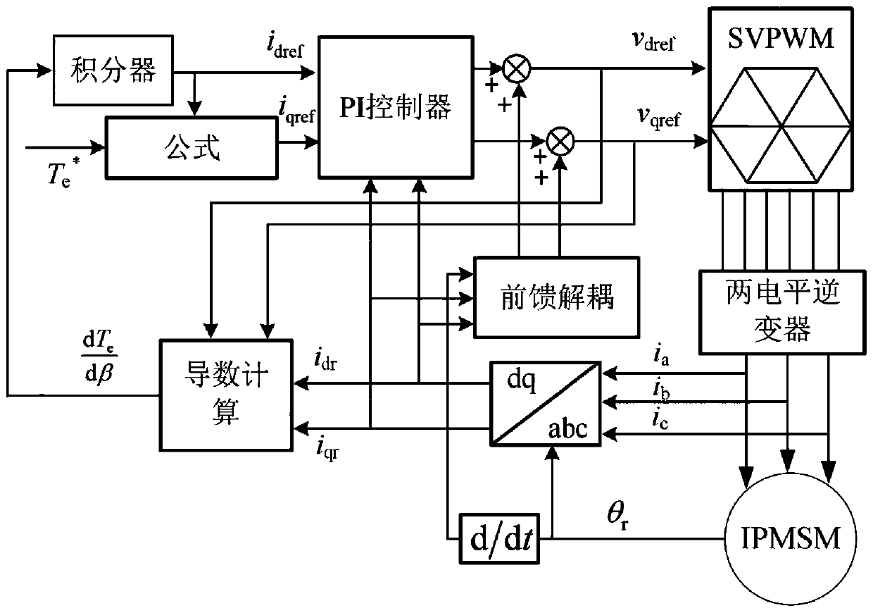
[0066] Such as figure 1 As shown, the maximum torque-to-current ratio control method of the built-in permanent magnet synchronous motor based on virtual complementary square wave signal injection of the present invention includes the following steps:

[0067] 1) First, the three-phase stator current i of the motor is obtained by sampling a i b i c , and then obtain the current i in the d, q coordinate system through coordinate transformation dr i qr ; Obtain the rotor position angle θ and mechanical speed ω of the motor through the resolver installed on the motor r .

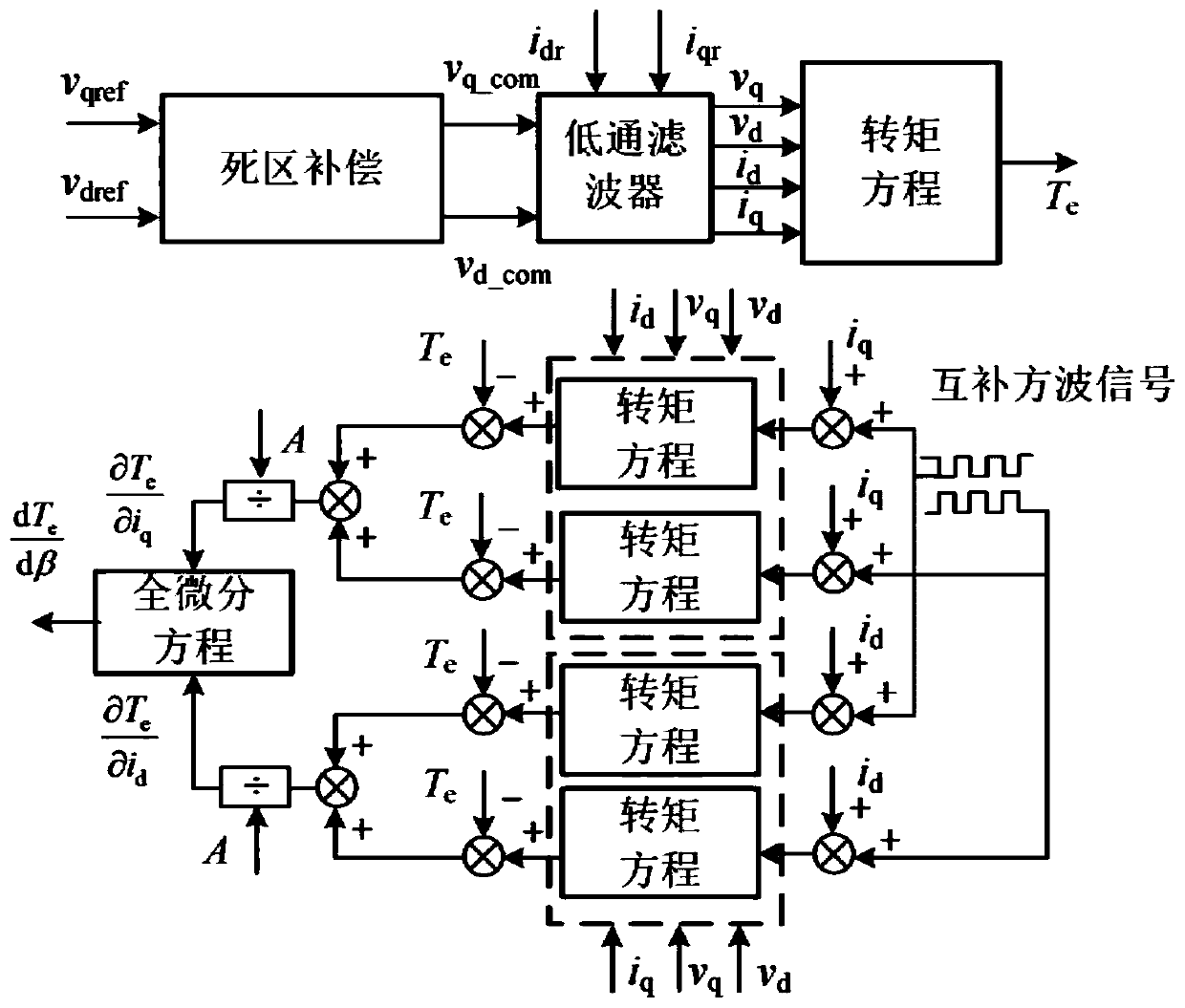
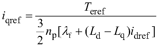
[0068] 2) will extract the dT e The / dβ information is used as the input of the integrator to generate the given value i of the d-axis current dref , at a given torque T eref Next, the given value i of the q-axis current qref Generated by the following formula...


PUM


Abstract

The invention discloses a maximum torque current ratio control method for a built-in permanent magnet synchronous motor. The method comprises the following steps: 1) obtaining three-phase stator currents ia, ib and ic of a motor through sampling, then, obtaining currents idr and iqr under d and q coordinate systems through coordinate transformation, and obtaining a rotor position angle theta and amechanical rotating speed omega r of the motor through a rotary transformer; 2) extracting derivative information dTe/dbeta of the torque to the current angle, taking the derivative information dTe/dbeta as the input of an integrator, generating a given value idref of the d-axis current, and obtaining a given value iqref of the q-axis current under the given torque Teref; adding a feedforward decoupling item to the output of the PI controller to obtain a d-axis stator voltage reference value vdref and a q-axis stator voltage reference value vqref; and 3) adopting a voltage space vector pulsewidth modulation method to obtain six paths of PWM pulse trigger signals, and controlling the two-level voltage source type inverter to work so as to drive the motor to rotate.

Description

technical field [0001] The invention relates to the field of motor control, in particular to a method for controlling the maximum torque-to-current ratio of a built-in permanent magnet synchronous motor based on virtual complementary square wave signal injection. Background technique [0002] The built-in permanent magnet synchronous motor (Permanent Magnet Synchronous Motor, PMSM) has the characteristics of compact structure and high power density, and is widely used in the drive system of electric vehicles. For the interior permanent magnet synchronous motor, in order to make full use of the reluctance torque, a maximum torque current ratio (Maximum Torque Per Ampere, MTPA) control method is often used. The determination of the maximum torque-to-current ratio operating point depends on the motor parameters. However, the parameters of the interior permanent magnet synchronous motor are affected by the environment, flux saturation and cross-coupling, showing a high degree o...

Claims


Application Information

Patent Timeline
IPC IPC(8): H02P21/14H02P25/026H02P27/08
CPCH02P21/14H02P25/026H02P27/08H02P2207/05
Inventor 史婷娜陈志伟阎彦王志强谷鑫
Owner TIANJIN UNIV
Why Eureka
Try Eureka