Monitoring the state of a temperature sensor

A temperature sensor and temperature monitoring technology, applied in thermometers, thermometer testing/calibration, instruments, etc., can solve the problems of precision and complexity of electronic devices, and achieve the effect of ensuring reliability, saving space and compact design

Active Publication Date: 2020-07-10
EHNDRESS KHAUZER GMBKH KO KG
View PDF9 Cites 0 Cited by
  • Summary
  • Abstract
  • Description
  • Claims
  • Application Information

AI Technical Summary

Problems solved by technology

However, such electronic devices are sophisticated and complex

Method used


Image

  • Monitoring the state of a temperature sensor
  • Monitoring the state of a temperature sensor
  • Monitoring the state of a temperature sensor

Examples


Embodiment Construction

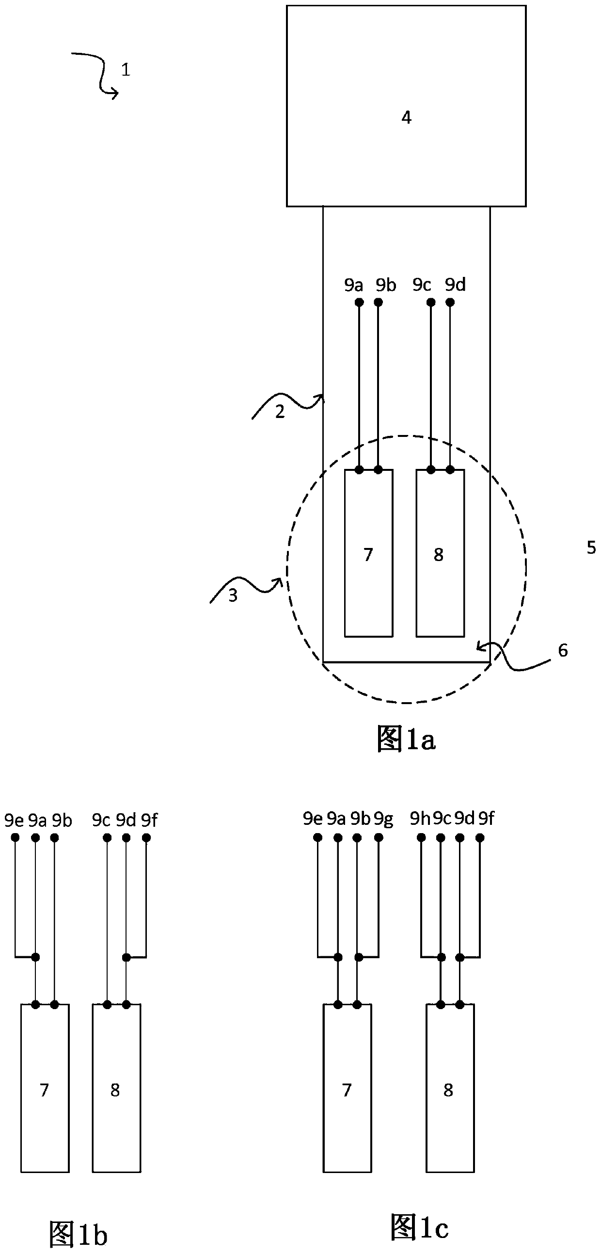
[0045] figure 1 Various schematic diagrams of a thermometer 1 according to the prior art are shown. figure 1 a shows a thermometer 1 , in particular a temperature transmitter, with a protective tube 2 and electronics 4 . The subregion of the protective tube 2 facing the medium 5 is also referred to in each case as the sensor head 3 . The interior of the sensor head 3 is filled with a filler, especially an electrically insulating filler 6 , especially cement.

[0046] Furthermore, a first temperature sensor 7 and a second temperature sensor 8 are arranged inside the sensor head 3 and each temperature sensor is electrically contacted via two connection lines 9 a , 9 b and 9 c , 9 d respectively, which lead to the electronics 4 . Other embodiments may include, for example, catheters for guiding the connecting wires 9a-9d. The temperature sensors 7 and 8 are, for example, resistive elements, in particular structurally identical resistive elements.

[0047] figure 1 The thermo...


PUM


Abstract

The invention relates to an apparatus (1) for determining and / or monitoring the temperature, comprising a first temperature sensor (17), a second temperature sensor (18) and electronics (14) which areconfigured to apply at least one electrical transmission signal (I S) in the form of an electrical current to the first temperature sensor (17) and / or the second temperature sensor (18) and to tap off at least one first and / or second electrical reception signal (U E1, U E2 ) in the form of an electrical voltage from the first temperature sensor (17) and / or the second temperature sensor (18). Theapparatus (1) also comprises at least six connection lines (19a-19f) for making contact, in particular electrical contact, with the first temperature sensor (17) and the second temperature sensor (18), wherein the connection lines (19a-19f) are arranged and configured in such a manner that the first temperature sensor (17) and the second temperature sensor (18) are connected in series and can havethe transmission signal (I S) applied thereto and in such a manner that the first reception signal (U E1) can be tapped off from the first temperature sensor (17) and / or the second reception signal (U E2) can be tapped off from the second temperature sensor (18).

Description

technical field [0001] The invention relates to a device for determining and / or monitoring the temperature of a medium having two sensor elements and electronics. The medium is located in a container, such as a box or a pipe, and the device, for example, can be introduced into or attached to the container. Background technique [0002] In many embodiments, thermometers are known from the prior art. Some thermometers measure temperature using the expansion of a liquid, gas, or solid with a known coefficient of expansion, while others measure temperature by relating the electrical conductivity of a material to temperature using, for example, a resistive element or a thermocouple. In contrast, in a pyrometer, the temperature of a substance is determined using its thermal radiation. The underlying measurement techniques in each case have been described in various publications. [0003] Thermometers with a resistive element usually comprise a so-called thin-film sensor element...

Claims


Application Information

Patent Timeline
Patent Type & Authority Applications(China)
IPC IPC(8): G01K7/16G01K15/00
CPCG01K7/16G01K15/00G01K7/20G01K7/18
Inventor 克里斯蒂安·普克迈克尔·科恩帕沃·弗尔多利亚克
Owner EHNDRESS KHAUZER GMBKH KO KG
Why Eureka
Try Eureka