Nail warehouse with high-strength nail pushing sheet installation structure, and stapler comprising nail warehouse

An installation structure and nail-pushing sheet technology, applied in the field of staplers, can solve the problems of low structural strength of the central guide, bending deformation, and the nail-pushing sheet cannot be pushed out normally, so as to avoid the bending phenomenon and eliminate the independent stress situation. Effect

Pending Publication Date: 2020-07-14
舒拓 +1
View PDF0 Cites 1 Cited by
  • Summary
  • Abstract
  • Description
  • Claims
  • Application Information

AI Technical Summary

Problems solved by technology

Depend on figure 2 As shown in , it can be seen that the central guide is placed in the housing cavity in isolation, and it is made of plastic, so the central guide has low structural strength. Therefore, during the firing process, the central guide is subjected to an oblique force Bending deformation also occurs, which leads to the failure of the pusher piece to be pushed out normally, thereby affecting the normal operation of the combined suture process

Method used


Image

  • Nail warehouse with high-strength nail pushing sheet installation structure, and stapler comprising nail warehouse
  • Nail warehouse with high-strength nail pushing sheet installation structure, and stapler comprising nail warehouse
  • Nail warehouse with high-strength nail pushing sheet installation structure, and stapler comprising nail warehouse

Examples


Embodiment Construction

[0021] In the description of the present invention, it should be understood that the orientations or positional relationships indicated by the terms "front", "rear", "left", "right", "upper" and "lower" are based on those shown in the accompanying drawings. Orientation or positional relationship is only for the convenience of describing the present invention and simplifying the description, and does not indicate or imply that the referred device or element must have a specific orientation, be constructed and operated in a specific orientation, and thus should not be construed as a limitation of the present invention.

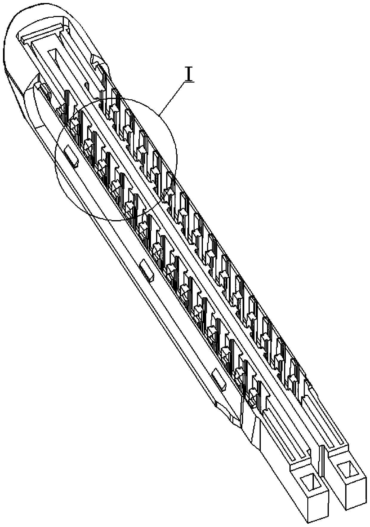
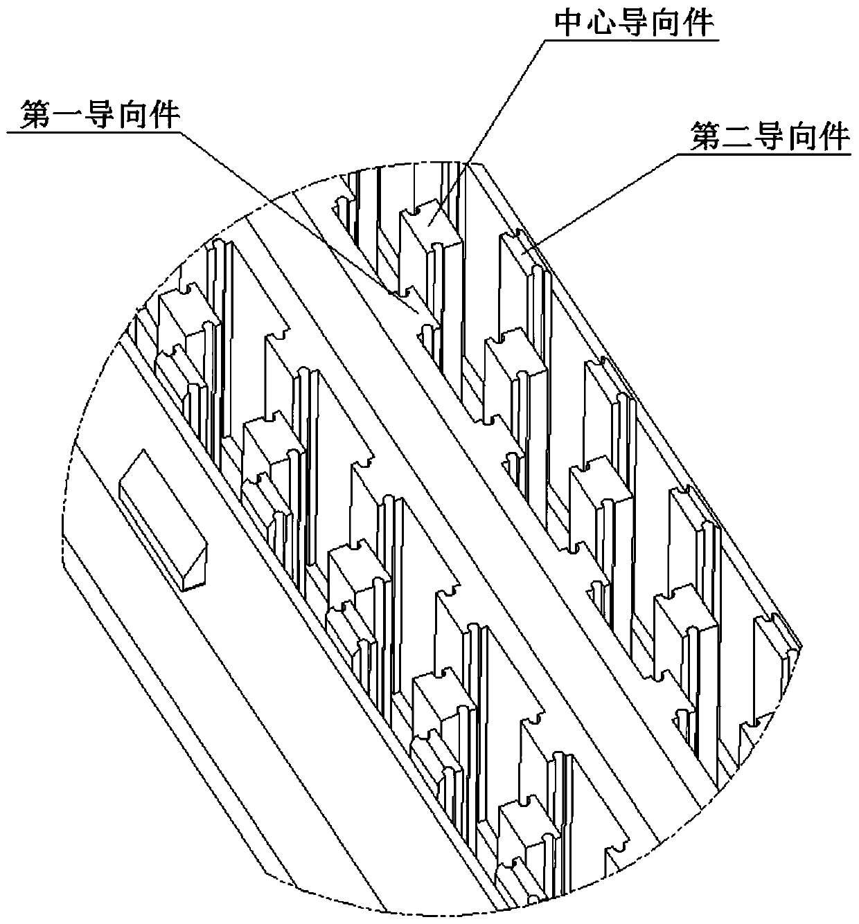
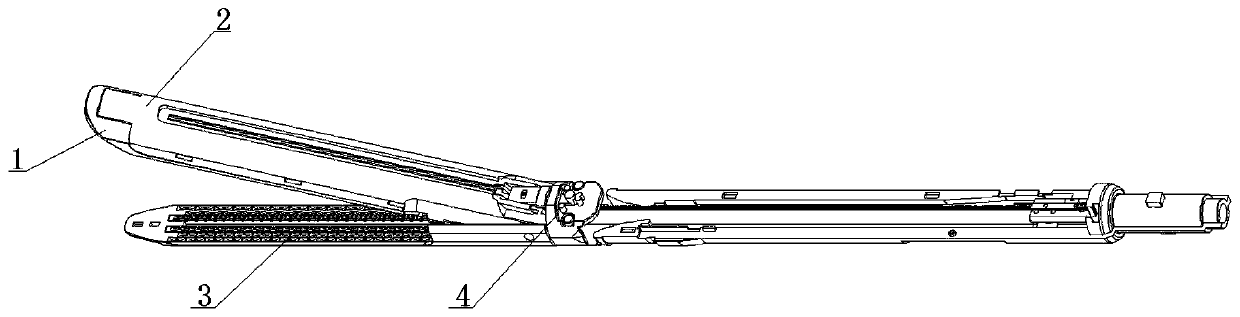
[0022] Below in conjunction with specific embodiment, content of the present invention is described in further detail, image 3 The three-dimensional schematic diagram of the stapler in the present invention is shown. It can be seen that it is mainly composed of several parts such as a staple cartridge 1, a staple cartridge frame 2, an anvil 3 and an adapter 4, w...


PUM


Abstract

The invention relates to a nail warehouse with a high-strength nail pushing sheet installation structure. The nail warehouse with the high-strength nail pushing sheet installation structure comprisesa nail warehouse body; a feeding groove and containing cavities used for containing a nail pushing sheet are arranged on the nail warehouse body; the number of the containing cavities is 2; the two containing cavities are symmetrically distributed at the left and right sides of the feeding groove; for the containing cavity at the right side, a guide assembly for guiding the nail pushing sheet is arranged therein; the guide assembly comprises a first guide part, centre guide parts, a second guide part and a reinforcing arm, wherein the centre guide parts are formed by upwardly extending from the bottom wall of the containing cavity; the reinforcing arm is also formed by upwardly extending from the bottom wall of the containing cavity, and connected between the centre guide parts; therefore,the various centre guide parts are mutually associated, so that an organic stressed whole is formed; the bending condition due to the fact that the centre guide parts are independently stressed is effectively stopped; and the centre guide parts can smoothly stretch out so as to execute tissue sewing operation. The invention further discloses a stapler.

Description

technical field [0001] The invention relates to the technical field of medical device manufacturing, in particular to a staple cartridge with a high-strength nail pusher mounting structure and a stapler including the same. Background technique [0002] In laparoscopic surgery and thoracoscopic surgery, laparoscopic cutting stapler is usually used for cutting and anastomosis of esophagus, stomach, duodenum, small intestine, colon, rectum, appendix, gallbladder, pancreas and spleen in the digestive tract, It is also used in cutting and anastomotic operations such as the lung and trachea in the respiratory tract, and in the bladder and uterus in the urogenital system. Through its application, it can greatly reduce the surgical wound, shorten the operation time and improve the quality of the operation. [0003] Generally speaking, the staple cartridge and the staple cartridge frame are fixed as a whole, and a cutting groove is provided along the length thereof. Place the tissue...

Claims


Application Information

Patent Timeline
Patent Type & Authority Applications(China)
IPC IPC(8): A61B17/072
CPCA61B17/07207A61B2017/07271
Inventor 舒拓
Owner 舒拓
Why Eureka
Try Eureka