A rotary toothed plate wall threaded hole chamfering machine
A threaded hole and rotary technology, which is applied in the field of rotary toothed disc wall threaded hole chamfering machines, can solve the problems of insufficient vertical deviation of the drill bit, increased chamfering workload, and deviated toothed disc thread angle.
- Summary
- Abstract
- Description
- Claims
- Application Information
AI Technical Summary
Problems solved by technology
Method used
Image
Examples
Embodiment 1
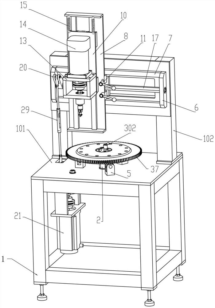
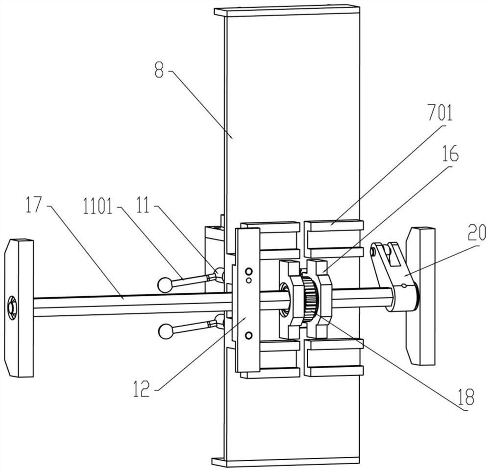
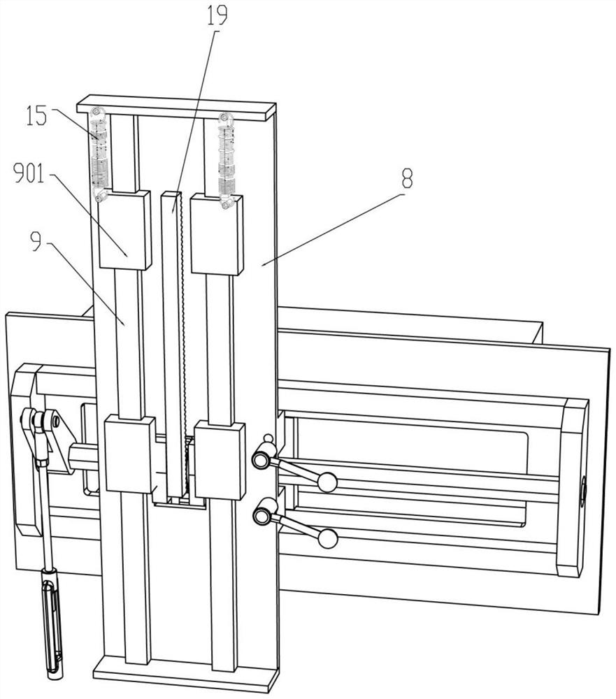
[0071] A rotary tooth plate wall threaded hole chamfering machine, such as Figure 1-5As shown, it includes a frame 1, a workbench 101, a load-bearing frame 102, a first rotating shaft 2, a locking sleeve 3, a locking rod 302, a tray 4, a pressure wheel 5, a threaded plate 6, a first guide rail 7, a second A guide block 701, the first mounting plate 8, the second guide rail 9, the second guide block 901, the second mounting plate 10, the locking device, the mounting seat 13, the electric drill 14, the first tension spring 15 and the toggle device, work The table 101 is fixed on the top of the frame 1, the load-bearing frame 102 is fixed on the rear side above the workbench 101, the first rotating shaft 2 is connected to the center of the workbench 101 in rotation, and is located in front of the load-bearing frame 102, and the locking sleeve 3 is fixed on the first At the end of the rotating shaft 2, eight threaded holes 301 are opened on the locking sleeve 3, and there are two...
Embodiment 2
[0074] On the basis of embodiment 1, a kind of rotary tooth disc wall threaded hole chamfering machine, such as Figure 1-5 As shown, the locking device includes a locking nut 11, a driving rod 1101 and a locking plate 12. The two locking nuts 11 are respectively screwed to the right front side of the first mounting plate 8, and the two driving rods 1101 are fixedly connected to the locking plate 12 respectively. The nut 11 and the locking plate 12 are arranged behind the first mounting plate 8 and between the two horizontal rows of first guide blocks 701 . The locking nut 11 is screwed to the locking plate 12 through the first mounting plate 8 .
[0075] When the electric drill 14 is not perpendicular to the chamfer of the gear plate 37, the locking nut 11 is loosened by the lever 1101, the locking plate 12 moves, and the first mounting plate is adjusted by sliding the first guide rail 7 and the first guide block 701 8 positions, so that the electric drill 14 is perpendicular...
Embodiment 3
[0079] On the basis of embodiment 1, a kind of rotary tooth disc wall threaded hole chamfering machine, such as Figure 1-5 As shown, a power assembly is also included, and the power assembly includes a servo motor 21, a mounting frame 22, a second rotating shaft 23, a second gear 24, a third gear 25, a first adjuster 26, a first V-shaped swing plate 28, The swing seat 27 and the second adjuster 29, the servo motor 21 are fixed on the left side in the frame 1, the mounting frame 22 is fixed below the workbench 101, the mounting frame 22 is connected to the output shaft of the servo motor 21 through a shaft coupling, and the second One end of the rotating shaft 23 is rotatably connected to the mounting frame 22, the other end is affixed to the shaft coupling above the servo motor 21, the second gear 24 is affixed to the second rotating shaft 23, and the third gear 25 is rotatably connected to the mounting frame 22. Two gears 24 mesh, one end of the first regulator 26 is univers...
PUM
 Abstract
Description
Claims
Application Information
 - R&D Engineer
- R&D Manager
- IP Professional
- Industry Leading Data Capabilities
- Powerful AI technology
- Patent DNA Extraction
Browse by: Latest US Patents, China's latest patents, Technical Efficacy Thesaurus, Application Domain, Technology Topic, Popular Technical Reports.
© 2024 PatSnap. All rights reserved.Legal|Privacy policy|Modern Slavery Act Transparency Statement|Sitemap|About US| Contact US: help@patsnap.com


