Engine and motor power coupling mechanism and automobile

A technology of power coupling and engine, applied in the direction of motor vehicles, hybrid vehicles, power units, etc., can solve the problems of poor power performance, large space occupation, complex structure, etc., and achieve the effects of good power performance, compact structure and small volume

Inactive Publication Date: 2020-07-14
ZHEJIANG GEELY AUTOMOBILE RES INST CO LTD +1
View PDF5 Cites 4 Cited by
  • Summary
  • Abstract
  • Description
  • Claims
  • Application Information

AI Technical Summary

Problems solved by technology

[0005] The technical problem to be solved by the present invention lies in the fact that the planetary gear mechanism in the power coupling mechanism in the prior art is mostly a double planetary gear mechanism, which has a complex structure, takes up a large space, and has poor power performance at low gears

Method used


Image

  • Engine and motor power coupling mechanism and automobile
  • Engine and motor power coupling mechanism and automobile
  • Engine and motor power coupling mechanism and automobile

Examples


Embodiment 1

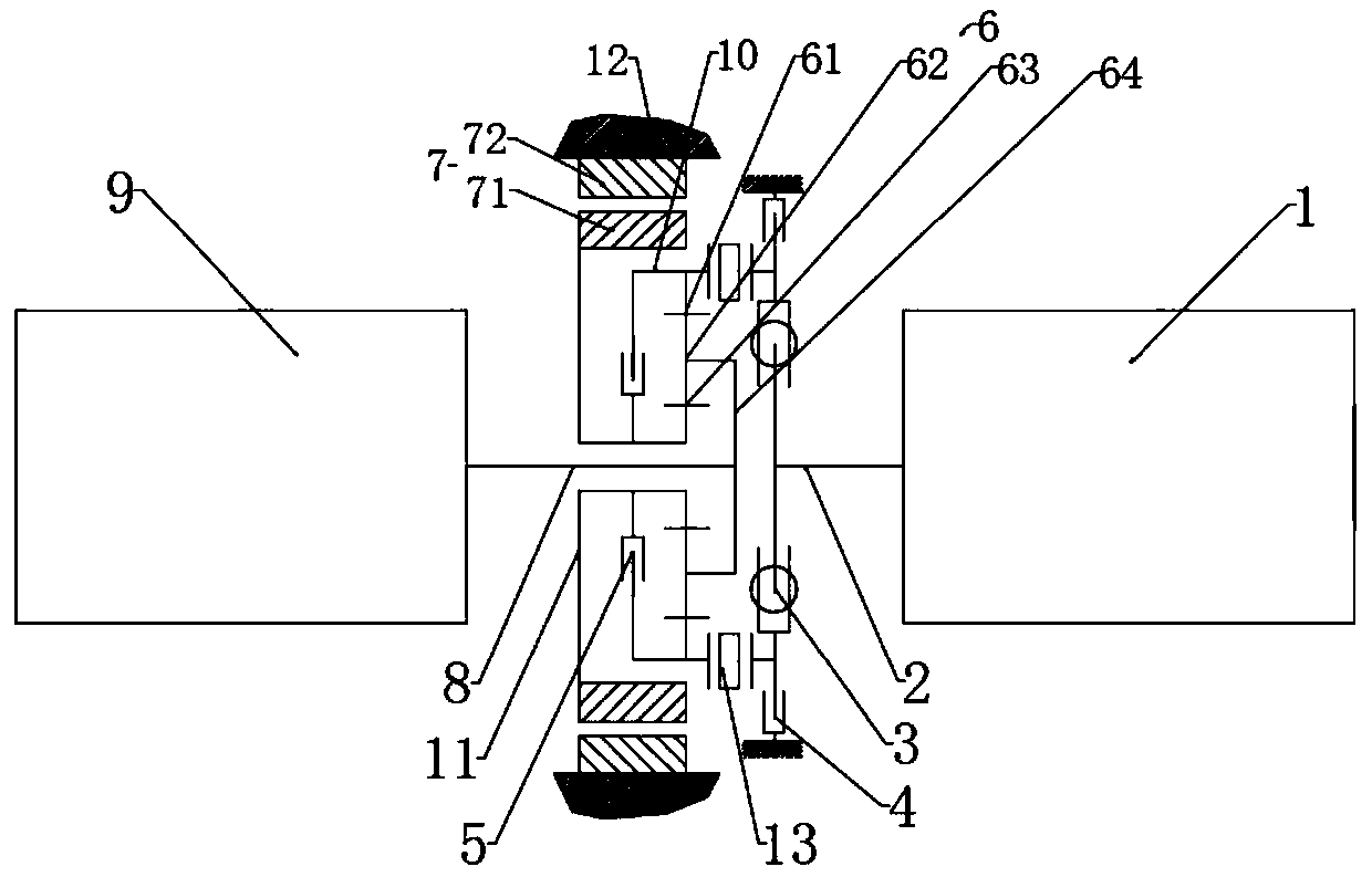
[0030] Such as figure 1 As shown, Embodiment 1 of the present invention provides a power coupling mechanism for an engine and a motor, including an engine 1, a motor 7, a one-way clutch 13, a brake 4, a lock-up clutch 5, a planetary gear mechanism 6 and an automatic transmission 9, and the planetary The gear mechanism 6 is a single planetary gear mechanism, including a ring gear 61, a planetary gear 62, a sun gear 63 and a planetary carrier 64. The planetary gear 62 is supported on the planetary carrier 64 through a bearing, and one end of the planetary gear 62 is connected to the planetary carrier 64. The ring gear 61 is meshed, the other end of the planetary gear 62 is meshed with the sun gear 63 , and the planet carrier 64 is connected with the input shaft 8 .

[0031] The engine 1 is connected to the ring gear connecting shaft 10 through the output shaft 2 and the one-way clutch 13, the ring gear connecting shaft 10 is connected to the ring gear 61, the driving end of the ...

Embodiment 2

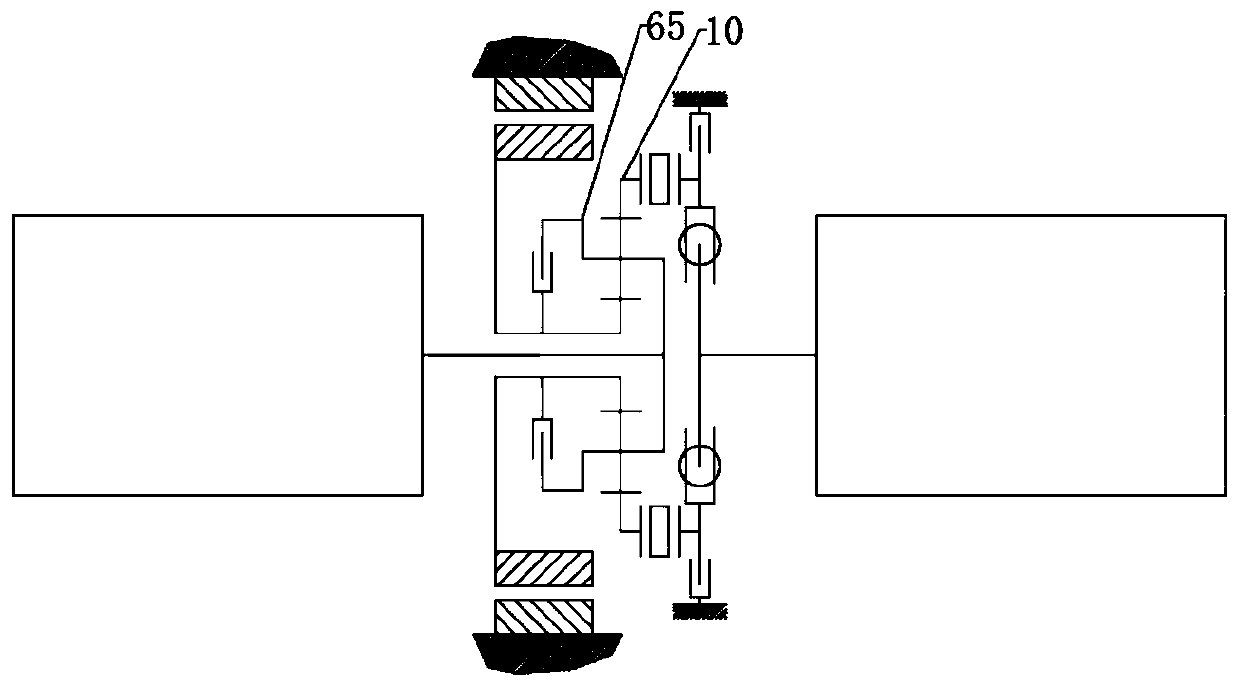
[0055] Such as figure 2 As shown, the difference between Embodiment 2 of the present invention and Embodiment 1 is that the planetary gear mechanism 6 includes a planetary gear connecting shaft 65, one end of the planetary gear connecting shaft 65 is connected to the planetary gear 62, and the planetary gear is connected to The other end of the shaft 65 is connected to the driven end of the lock-up clutch 5 . Specifically, the passive end of the lock-up clutch is integrally connected with the planetary carrier 64 and the input shaft through the planetary gear connecting shaft 65 and the planetary gear 62 . In practical applications, the motor power can be transmitted to the planetary gear mechanism through the planetary gear through the lock-up clutch 5 .

Embodiment 3

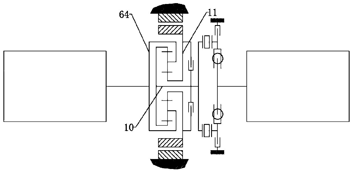
[0057] Such as image 3 As shown, the difference between Embodiment 3 of the present invention and Embodiment 1 is that one end of the ring gear connecting shaft 10 is connected to the ring gear 61, and the other end of the ring gear connecting shaft 10 is connected to the ring gear through the one-way clutch 13. The passive end of the brake 4 is connected as a whole, the gear connection shaft 10 is also connected to the driving end of the lock-up clutch 5, and the sun gear connection shaft 11 is connected to the passive end of the lock-up clutch 5 and the rotor respectively. 71 connections as one. Specifically, the lock-up clutch 5 and the motor 7 are arranged on the left side of the planetary gear mechanism 6 in Embodiment 1, and the lock-up clutch 5 and the motor 7 are arranged on the right side of the planetary gear mechanism 6 in Embodiment 3. The left and right sides are based on the directions in the accompanying drawings.


PUM


Abstract

The invention discloses an engine and motor power coupling mechanism and an automobile. The engine and motor power coupling mechanism comprises an engine, a motor, a one-way clutch, a brake, a lockupclutch and a planetary gear mechanism, wherein the planetary gear mechanism comprises a gear ring, a sun gear and a planet carrier; the engine is connected with the gear ring and the gear ring connecting shaft through an output shaft and the one-way clutch; one end of the brake is fixed to the shell, the other end of the brake is connected with the output shaft and the one-way clutch, and a rotorof the motor is connected with the sun gear and the lockup clutch into a whole through a sun gear connecting shaft; and the planetary gear mechanism is used for coupling power of the engine and the motor and is connected with an automatic transmission through the planet carrier and the input shaft. The mechanism has the advantages of being compact in structure and improving the power performance of the automobile at a low gear.

Description

technical field [0001] The invention relates to the technical field of automobile hybrid drive systems, in particular to an engine and motor power coupling mechanism and an automobile. Background technique [0002] In recent decades, the automobile industry of various countries in the world is facing the two major challenges of energy crisis and environmental protection. To this end, governments of various countries have formulated corresponding countermeasures, trying to develop a new generation of clean and energy-saving vehicles. With electric energy as the power source, non-polluting, clean and efficient electric vehicles have gradually entered the stage of history, and their development prospects are very attractive. Electric vehicle (EV) is an electric-driven road vehicle with a wide range of connotations, generally including battery electric vehicles or pure electric vehicles (BEV), hybrid electric vehicles (HEV) and fuel cell electric vehicles (FCEV). The bottlenec...

Claims


Application Information

Patent Timeline
Patent Type & Authority Applications(China)
IPC IPC(8): B60K6/365B60K6/24B60K6/26B60K6/38B60K6/547
CPCB60K6/24B60K6/26B60K6/365B60K6/38B60K6/547Y02T10/62
Inventor 梁健
Owner ZHEJIANG GEELY AUTOMOBILE RES INST CO LTD
Why Eureka
Try Eureka