Check patentability & draft patents in minutes with Patsnap Eureka AI!

A rolling glass melting furnace and its strengthening method

A glass melting furnace and calendering technology, applied in glass calendering, glass molding, glass furnace equipment, etc., can solve problems such as high-temperature gas escaping, collapse, and burning supporting steel components, and achieve the effect of height reduction

Active Publication Date: 2022-04-22
QINHUANGDAO GLASS IND RES & DESIGN INST
View PDF4 Cites 0 Cited by
  • Summary
  • Abstract
  • Description
  • Claims
  • Application Information

AI Technical Summary

Problems solved by technology

There is an expansion straight seam 14 at the contact point between the branch passage 7 and the cross passage breast wall 2, high-temperature gas will come out during the kiln and normal operation, and it cannot be sealed, and the high-temperature gas will burn the supporting steel of the cross passage 1 Component 13, causing safety problems in the horizontal passageway 1, which may lead to its collapse in severe cases
At the same time, during the baking kiln or normal production process, the cross passage parapet 2 with a length of 45 meters and a height of 1.8 meters has a relatively high center of gravity, and the inner and outer sides of the cross passage breast wall 2 on the side directly in contact with the branch passage 7 are in a high-temperature environment. Both sides are subjected to physical erosion and chemical erosion of high-temperature gas, which is easy to be burned and deformed, and cannot be repaired in a hot state, eventually leading to collapse
If one of the above two situations occurs, the production will be suspended, and the glass melting furnace needs to be released in advance to cold repair the glass melting furnace, resulting in a decrease in glass production efficiency and an increase in production costs.

Method used


Image

  • A rolling glass melting furnace and its strengthening method
  • A rolling glass melting furnace and its strengthening method
  • A rolling glass melting furnace and its strengthening method

Examples


Embodiment Construction

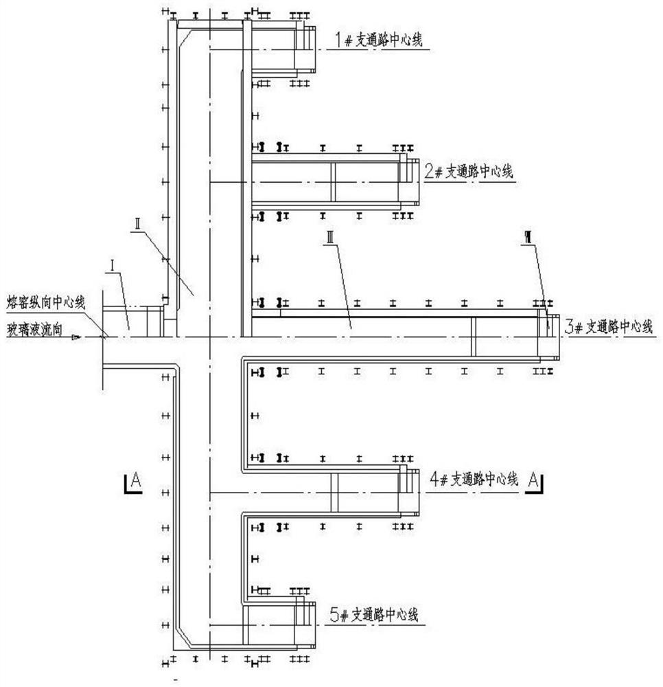
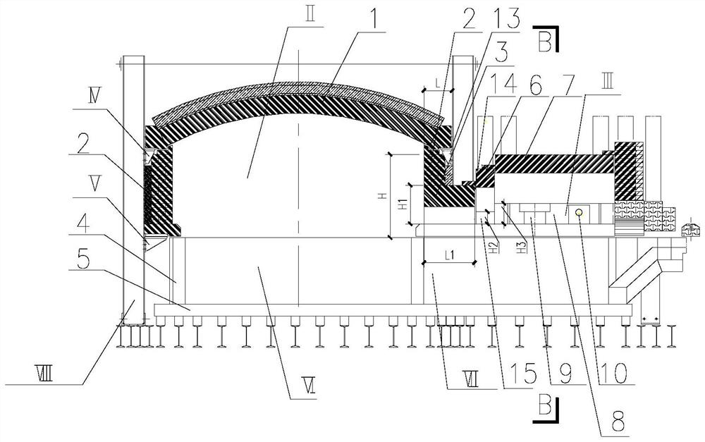
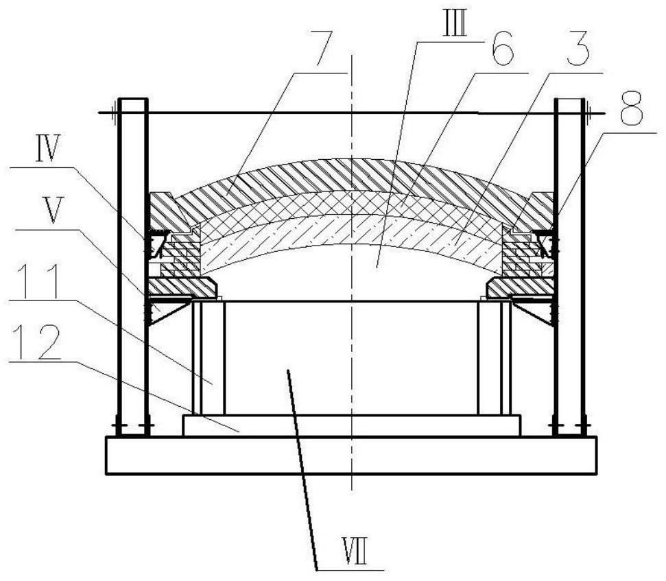
[0024] In order to prolong the service life of the glass melting kiln for the photovoltaic glass of the calendering process, the present invention adds a transition wall between the branch channel entrance wall and the branch channel wall as a reinforcement device, and the height of the transition wall (the height of the wall all refers to the The distance from the top to the top surface of the glass pool wall) is 235mm-610mm lower than the height of the branch passage, and 150mm-240mm higher than the height of the branch passage entrance. The entrance of the branch passage is built on the top surface of the glass liquid pool of the horizontal passage, which is equivalent to the height of the breast wall is 0, and the height between the entrance and the top of the bridge is 610mm-630mm from the top of the pool wall; the transitional bridge is built on the transitional breast wall , parapet height H 2 180mm-200mm, the height between the transitional crown and the parapet top is...


PUM

PropertyMeasurementUnit
heightaaaaaaaaaa
lengthaaaaaaaaaa
lengthaaaaaaaaaa

Abstract

The invention discloses a rolling glass melting furnace and a strengthening method thereof. A transitional arch structure is arranged between the branch passage and the transverse passage, and the transition arch structure includes a section of transition interposed between the parapet of the transverse passage and the parapet of the branch passage. The parapet, the transition parapet and the parapet of the branch passage are integrally built, and the height is lower than that of the parapet of the branch passage, including the transition bridge across the transition parapet; the height of the entrance gate of the branch passage, the transition gate and the branch passage are increased in turn, forming a stepped Structural structure. In this way, the high-temperature gas emitted from the expansion straight joint can be avoided from ablation of the supporting steel member of the horizontal passage, and the expansion straight joint can also be sealed; and the outside of the lateral passage parapet on the side of the branch passage is exposed to the air, and the air can The parapet plays a cooling role.

Description

technical field [0001] The invention relates to the technical field of glass production, in particular to a rolling glass melting furnace and a method for strengthening the rolling glass melting furnace. Background technique [0002] Photovoltaic glass is a high transmittance glass material used in photovoltaic modules, which is produced by rolling process. Because the greater the melting capacity of the glass melting furnace, the lower its energy consumption, and the lower the production cost of the corresponding glass. Therefore, the melting furnace used for the production of photovoltaic glass is a furnace with multiple lines (multiple branch passages), that is, multiple branch passages are set on one side of a horizontal passage and perpendicular to the horizontal passage, and each branch passage is connected in parallel to the horizontal passage. superior. In normal production, glass raw materials are first melted into molten glass at high temperature in the melting p...

Claims


Application Information

Patent Timeline
Patent Type & Authority Patents(China)
IPC IPC(8): C03B5/04C03B5/42C03B13/00
CPCC03B5/04C03B5/42C03B13/00
Inventor 牟竹生黄治斌
Owner QINHUANGDAO GLASS IND RES & DESIGN INST
Features
  • R&D
  • Intellectual Property
  • Life Sciences
  • Materials
  • Tech Scout
  • Unparalleled Data Quality
  • Higher Quality Content
  • 60% Fewer Hallucinations
Learn More