Wire drawing device and method for reducing surface defects of optical fiber

An optical fiber and wire drawing technology, used in glass manufacturing equipment, glass production, manufacturing tools, etc., can solve the problems of fiber silk slipping and twisting or drawing wire diameter, scalding rubber drawing wheel, unable to draw wire, etc., to improve surface quality and , The effect of reducing the damage of the cortex and stabilizing the drawing process

Active Publication Date: 2020-07-14
CHINA BUILDING MATERIALS ACAD
View PDF4 Cites 5 Cited by
  • Summary
  • Abstract
  • Description
  • Claims
  • Application Information

AI Technical Summary

Problems solved by technology

Wheel drawing mainly relies on the rotational friction of the rubber drawing wheel to realize the drawing of optical fiber filaments. During the drawing process, the optical fiber is in direct contact with the rubber surface of the drawing wheel. Due to the frictional contact process, the surface of the optical fiber filament is extremely It is easy to be damaged. When the drawing temperature is high, it is easy to burn the surface of the rubber drawing wheel and cause impurity pollution on the surface of the optical fiber; when the drawing temperature is low, it is easy to slip with the rubber drawing wheel and cannot be drawn. Or cause the surface of the optical fiber filament to produce cortex glass wear and other phenomena
Pulling mainly relies on the rubber synchronous belt to contact the optical fiber, which is also very prone to fiber slippage or twisting of the optical fiber during the drawing process or the phenomenon of unstable drawing wire diameter, which requires human intervention During the drawing process, the surface of the optical fiber is damaged, colloidal particles are adhered to impurities, or the verticality and concentricity of the drawn optical fiber are deteriorated, resulting in a decline in the drawing quality of the optical fiber.

Method used


Image

  • Wire drawing device and method for reducing surface defects of optical fiber

Examples


Embodiment Construction

[0014] In order to make the purpose, technical solutions and advantages of the embodiments of the present invention clearer, the technical solutions in the embodiments of the present invention will be clearly and completely described below in conjunction with the drawings in the embodiments of the present invention. Obviously, the described embodiments It is a part of embodiments of the present invention, but not all embodiments. Based on the embodiments of the present invention, all other embodiments obtained by persons of ordinary skill in the art without making creative efforts belong to the protection scope of the present invention.

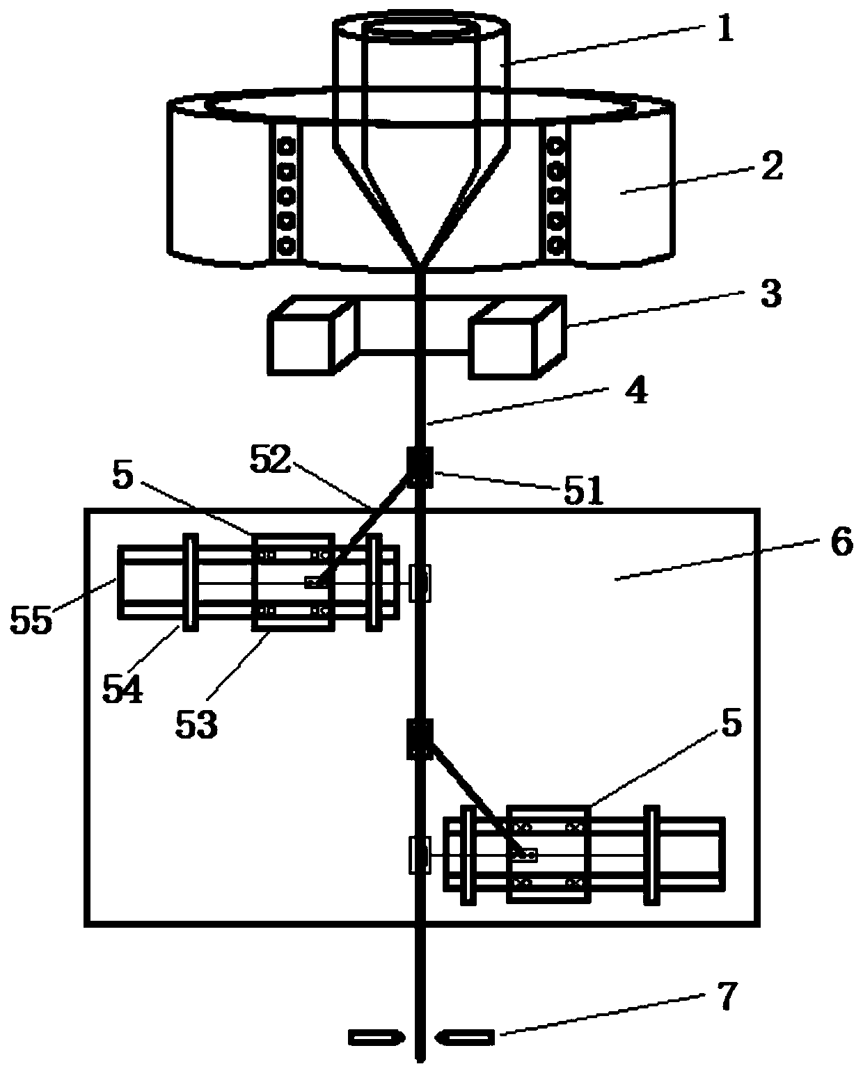
[0015] see figure 1 , a wire drawing device for reducing surface defects of optical fiber filaments, comprising a wire drawing mechanism 5;

[0016] The wire drawing mechanism 5 includes a gripper 51 and a mechanical arm 52 capable of moving up and down. One end of the robotic arm 52 is connected with the gripper 51 , and the gripper 51 is u...


PUM

PropertyMeasurementUnit
diameteraaaaaaaaaa

Abstract

The invention discloses a wire drawing device and method for reducing surface defects of an optical fiber. The wire drawing device comprises a wire drawing mechanism, the wire drawing mechanism comprises a clamping jaw and a mechanical arm capable of moving up and down, one end of the mechanical arm is connected with the clamping jaw, and the clamping jaw is used for clamping the optical fiber fortraction drawing. The drawing method comprises the following steps: (1) melting, drawing and drooping an optical fiber preform in an optical fiber drawing furnace to obtain an optical fiber filament,and clamping the optical fiber filament by a mechanical clamping jaw; (2) moving the displacement slide block, and moving the mechanical arm up and down to draw the optical fiber filament; and (3) carrying out fixed-length cutting on the dragged optical fiber through a cutter. The clamping jaws are in point contact with the optical fiber for traction and drawing, so that the drawing process of the optical fiber is more stable, surface contact and skin layer damage of the optical fiber in the drawing process are reduced, and the drawing surface quality of the optical fiber and the stability ofthe fiber diameter are improved.

Description

technical field [0001] The invention relates to the technical field of optical fiber manufacturing and processing, in particular to a drawing device and method for reducing surface defects of optical fiber filaments. Background technique [0002] Optical fiber imaging components, including optical fiber panels, optical fiber inverters, optical fiber cones, optical fiber imaging bundles, and microchannel plates, are photoelectric imaging components with excellent performance, with simple structure, small size, and light weight. , high resolution, large numerical aperture, small inter-stage coupling loss, clear and true image transmission, high light transmission efficiency, optical zero thickness in image transmission, and improved edge image quality. Optical fiber image transmission components are widely used in various cathode ray tubes, camera tubes, charge-coupled device (CCD, Charge-coupled Device) couplings, medical device display screens and high-speed High-definition...

Claims


Application Information

Patent Timeline
Patent Type & Authority Applications(China)
IPC IPC(8): C03B37/03C03B37/16
CPCC03B37/032C03B37/16Y02P40/57
Inventor 张磊贾金升赵越张弦汤晓峰石钰许慧超于浩洋张敬樊志恒宋普光王爱新洪常华
Owner CHINA BUILDING MATERIALS ACAD
Why Eureka
Try Eureka