
Shallow layer foundation pit dewatering construction method for water-rich pebble bed

A construction method and pebble layer technology are applied in the field of shallow foundation pit dewatering construction, which can solve the problems of water seepage, high water permeability, affecting the construction process, affecting the construction progress, etc., so as to improve drainage efficiency, improve precipitation efficiency and improve drainage. The effect of efficiency

Active Publication Date: 2020-07-14
中建七局第一建筑有限公司
View PDF11 Cites 4 Cited by
  • Summary
  • Abstract
  • Description
  • Claims
  • Application Information

AI Technical Summary

Problems solved by technology

[0002] With the rapid development of my country's construction industry, the scale of construction continues to expand, and the geological conditions involved are becoming more diverse. Due to the particularity of the geographical environment in the area of ​​rivers and their tributaries, the geological layers mostly form a structure of silt layer, pebble layer and mudstone layer from top to bottom. The large porosity of the pebble layer leads to its high water seepage and water permeability. , and the groundwater near the river is relatively rich, and the groundwater is more likely to enter the foundation pit through the pebble layer during the construction process, which increases the workload of foundation pit dewatering, further affects the construction progress, and increases the related costs in the construction; at the same time, the pebble layer The overall stability is low, and it is more likely to collapse during the construction of the foundation pit, which affects the construction process and also poses a greater safety hazard
[0003] In the existing technology, in the precipitation of foundation pits in water-rich pebble layers, in order to enhance the precipitation effect, the method of intensively drilling holes around the foundation pit is often used. This method can improve the precipitation effect to a certain extent, but the intensive drilling method is in the While increasing the cost, it will also cause certain damage to the stability of the relatively loose pebble layer structure;
[0004] And the dewatering wells can only discharge groundwater within a certain range nearby. When the density of the dewatering wells is too high, the convergence speed of the groundwater is lower than the drainage speed of the dewatering wells. After multiple dewatering wells discharge the groundwater near the surrounding sides of the foundation pit, it will Stop working until the groundwater re-converges and start working again, and the intermittent working mode of the precipitation well during the drainage process is inefficient;
[0005] Due to the excessively large gaps in the pebble layer itself, even if the method of increasing the number of precipitation wells is used to drain the groundwater intensively during the drainage process, a considerable part of the groundwater will still enter the foundation pit through the gaps between the pebble layers between the precipitation wells. , during the construction of the foundation pit in the later period, the drainage work for the groundwater entering the foundation pit will be increased
[0006] In order to solve the water seepage problem of the pebble layer involved in the above scheme, some construction units will adopt the construction method of cast-in-situ pile + water-stop curtain, which is relatively expensive and is mostly suitable for deep foundation pit construction. The pit construction will greatly exceed the original construction budget

Method used


Image

  • Shallow layer foundation pit dewatering construction method for water-rich pebble bed
  • Shallow layer foundation pit dewatering construction method for water-rich pebble bed
  • Shallow layer foundation pit dewatering construction method for water-rich pebble bed

Examples


Embodiment Construction

[0051] The following will clearly and completely describe the technical solutions in the embodiments of the present invention with reference to the accompanying drawings in the embodiments of the present invention. Obviously, the described embodiments are only some, not all, embodiments of the present invention. Based on the embodiments of the present invention, all other embodiments obtained by persons of ordinary skill in the art without making creative efforts belong to the protection scope of the present invention.

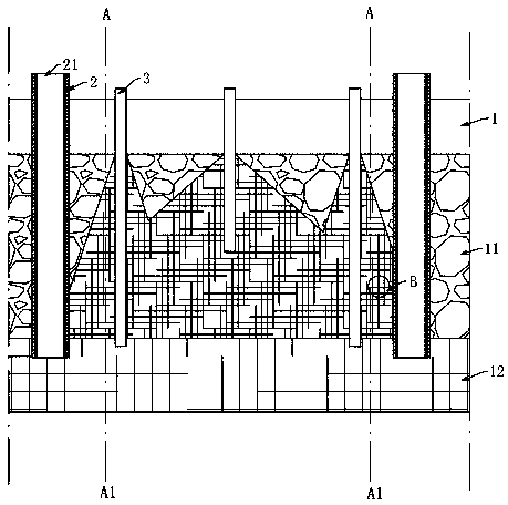
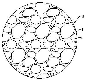
[0052] The present invention is used for the specific embodiment of the shallow foundation pit dewatering construction method of water-rich pebble layer 11, as Figure 1-3 Shown:

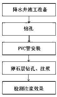
[0053] The shallow foundation pit dewatering construction method used for the water-rich pebble layer 11, the specific construction steps are as follows:

[0054] S1. Preparation for the construction of dewatering wells. According to the actual construction plan of the dewatering w...


PUM

PropertyMeasurementUnit
Diameteraaaaaaaaaa

Abstract

The invention provides a shallow layer foundation pit dewatering construction method for a water-rich pebble bed, and relates to the field of dewatering of a water-rich pebble bed foundation pit. Theshallow layer foundation pit dewatering construction method comprises the following steps that S1, dewatering well construction is prepared; S2, drilling is carried out, and a drilling machine takes place to drill at a preset dewatering well position and lower a well pipe; S3, a PVC pipe is installed in the well pipe; S4, drilling and slip casting are carried out on side pebble bed of a foundationpit; S5, the grouting effect in the pebble bed is detected; and S6, the dewatering work is started. According to the shallow layer foundation pit dewatering construction method, an anti-seepage curtain is formed between two dewatering wells to dredge underground water into the dewatering radii of the dewatering wells, the shallow layer foundation pit dewatering construction method has the advantages of good dewatering effect and high dewatering efficiency, meanwhile, the construction cost is saved, and the construction cycle is shortened.

Description

technical field [0001] The invention relates to a construction method for dewatering a shallow foundation pit in a water-rich pebble layer. Background technique [0002] With the rapid development of my country's construction industry, the scale of construction continues to expand, and the geological conditions involved are becoming more diverse. At the same time, as people's requirements for the living environment gradually increase, residential buildings near rivers, rivers and their tributaries gradually rise. Due to the particularity of the geographical environment in the area of ​​rivers and their tributaries, the geological layers mostly form a structure of silt layer, pebble layer and mudstone layer from top to bottom. The large porosity of the pebble layer leads to its high water seepage and permeability. , and the groundwater near the river is relatively abundant, the groundwater is more likely to enter the foundation pit through the pebble layer during the constructi...

Claims


Application Information

Patent Timeline
IPC IPC(8): E02D19/06E02D19/10E02D19/16
CPCE02D19/06E02D19/10E02D19/16
Inventor 徐洪瑞刘楠楠孟令举曹维存寇小勇王俊锋曹秀玲孙辉马原宋磊于猛
Owner 中建七局第一建筑有限公司
Features
  • Generate Ideas
  • Intellectual Property
  • Life Sciences
  • Materials
  • Tech Scout
  • Unparalleled Data Quality
  • Higher Quality Content
  • 60% Fewer Hallucinations
Learn More