Eureka AIR delivers breakthrough ideas for toughest innovation challenges, trusted by R&D personnel around the world.

Differential pressure valve assembly

A valve chamber, valve seat technology, applied in valve devices, valve operation/release devices, valve lifters, etc., to solve problems such as reduced efficiency, unpredictability, and limitations

Pending Publication Date: 2020-07-14
DANFOSS AS
View PDF6 Cites 0 Cited by
  • Summary
  • Abstract
  • Description
  • Claims
  • Application Information

AI Technical Summary

Problems solved by technology

[0003] However, the operation of these valves can be affected by various causes such as debris in the working fluid that has deposited on the closing or valve elements adapted to respond to pressure changes, etc.
This will result in reduced efficiency but also unpredictable valves where actual operation does not match expectations and where unpredictable valves may be limited in their operating range

Method used


Image

  • Differential pressure valve assembly
  • Differential pressure valve assembly
  • Differential pressure valve assembly

Examples


Embodiment Construction

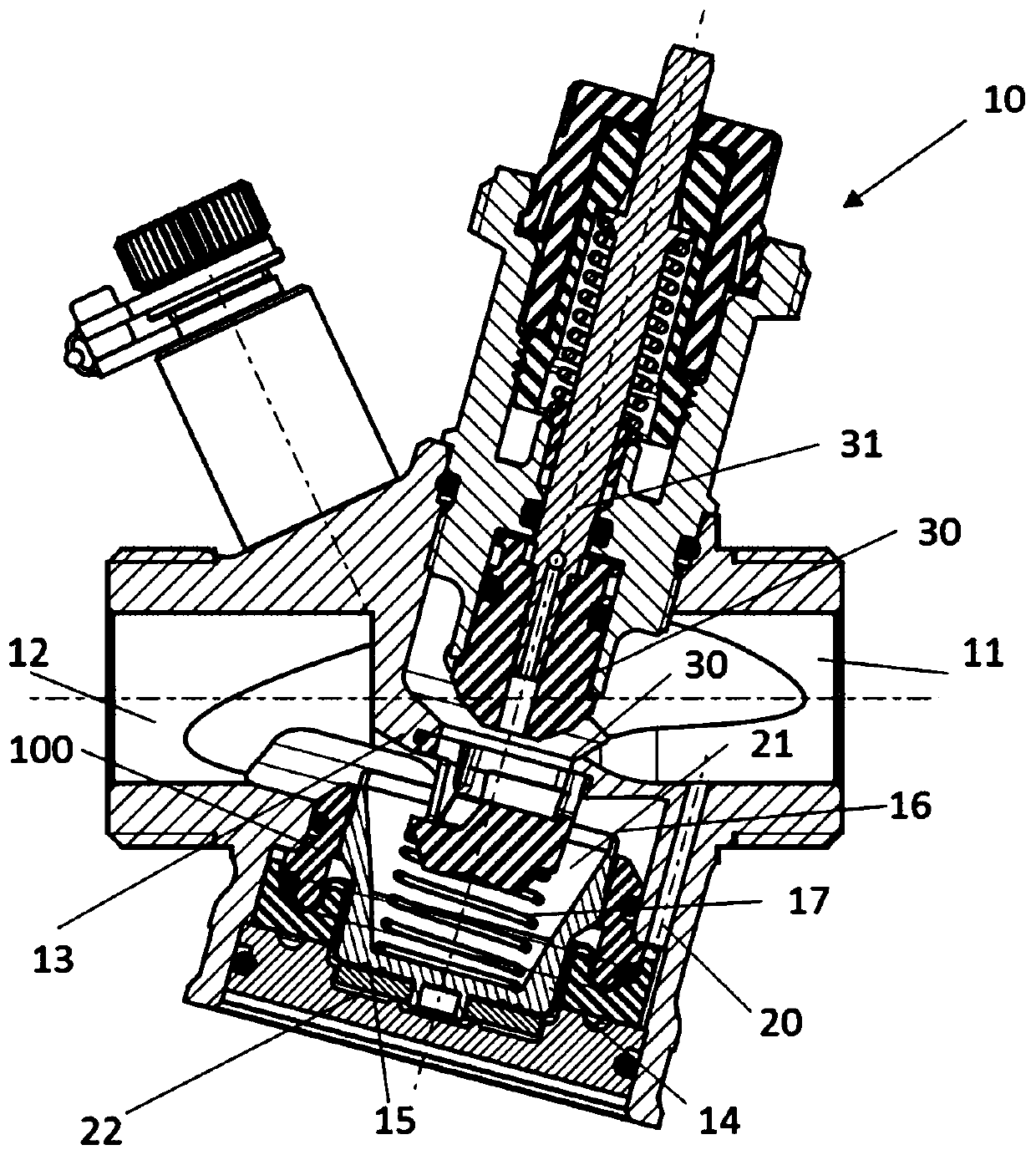
[0023] figure 1 A pressure control valve 10 is schematically shown comprising a gate 14 or valve element arranged in a valve chamber 16 positioned between at least one fluid inlet 11 and at least one fluid outlet 12 . The gate 14 is adapted to move relative to the valve seat 13 which defines a first degree of opening of the pressure control valve 10 based on the distance between the two parts. Fluid thus passes from the inlet 11 through the pressure control valve 10 to the outlet 12 with a flow rate regulated in the usual manner through the valve opening formed between the valve seat 13 and the gate 14 .

[0024] In the figure, an optional further flow control valve is located between said inlet 11 and outlet 12 formed by a flow control valve element 30 cooperating with a second valve seat 32 and connected at the valve At the first end of the pin 31, the second end of the valve pin is optionally connected to an actuator.

[0025] The gate 14 is fixed to a diaphragm 15 which ...


PUM


Abstract

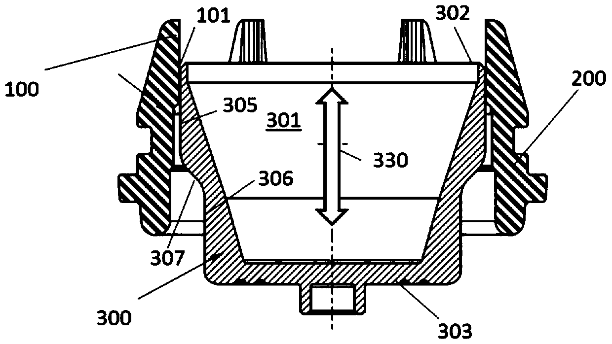
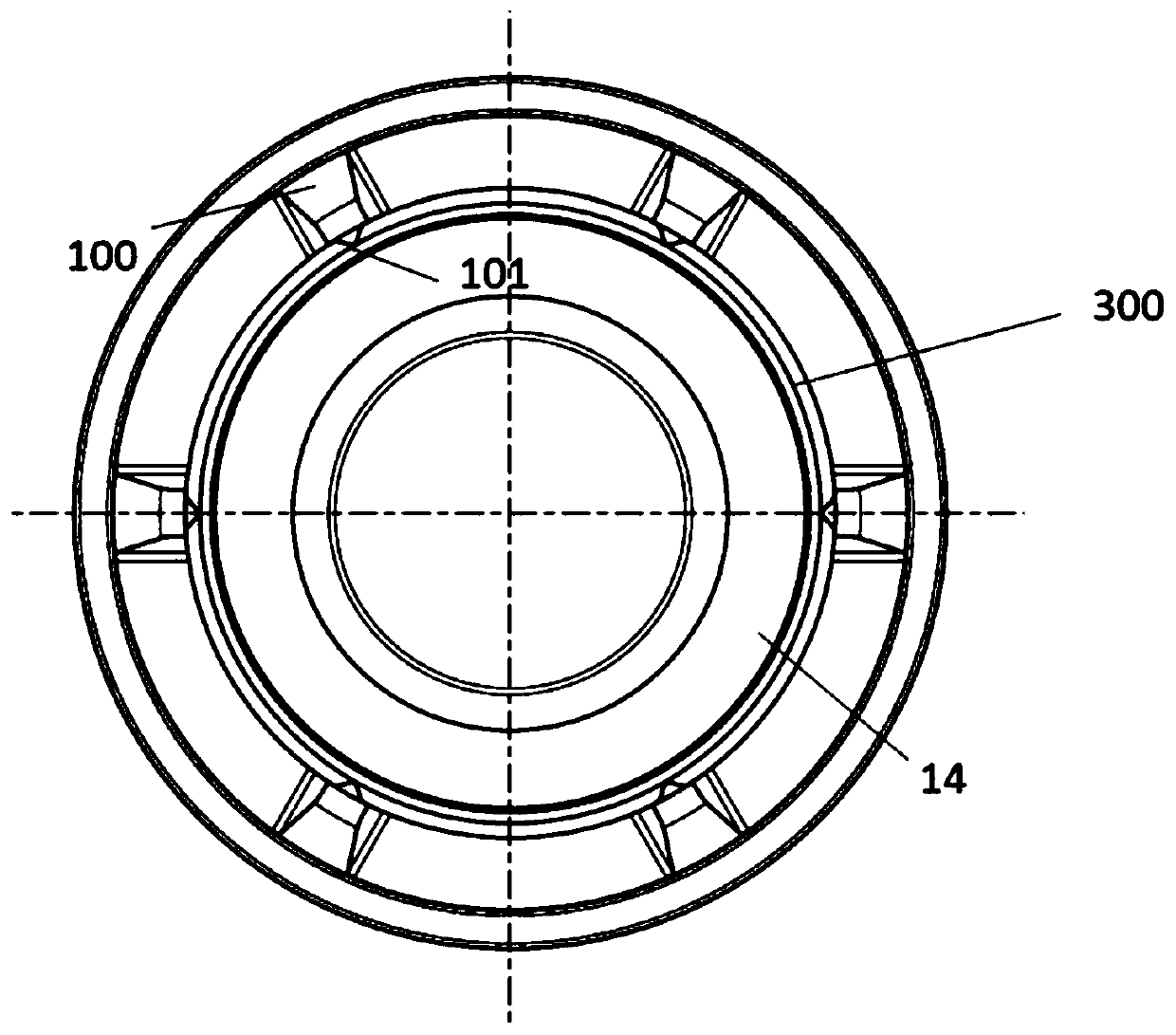
The invention relates to a pressure control valve. The pressure control valve comprises: a gate located in a valve chamber between one fluid inlet and one fluid outlet, wherein the gate is movable relative to valve seat defining first opening degree of pressure control valve; and a diaphragm connected with the gate, wherein the membrane deflects when changes in differential pressure on the membrane, and then the position of the gate relative to the pressure-sensitive valve seat is changed. The gate guide inside the valve chamber comprises a plurality of contact parts in contact with the outerwall of the gate and arranged on the circumference of the gate.

Description

technical field [0001] The invention relates to a valve arrangement, such as in particular a heat exchanger valve arrangement, having a pressure control valve comprising a valve element cooperating with a throttle element and controlling a pressure difference. Background technique [0002] In heating systems, the flow rate may be controlled by flow controllers such as valves, where these flow controllers may be pressure independent valves that increase system efficiency. [0003] However, the operation of these valves may be affected by various causes such as debris in the working fluid that has deposited on the closing or valve elements adapted to respond to pressure changes. This will result in reduced efficiency, but also in an unpredictable valve where actual operation does not match expectations and where the unpredictable valve may be limited in its operating range. [0004] The object of the invention is to prevent, by fouling etc., the closure element from being res...

Claims


Application Information

Patent Timeline
IPC IPC(8): F16K17/04F16K31/126
CPCF16K17/04F16K31/126G05D16/00G05D16/08G05D7/0106F16K1/10F16K1/52F16K7/07
Inventor 彼特·诺兹托马兹·扎加尔朱尔·雷伯尼克
Owner DANFOSS AS
Why Eureka
Eureka Blog
Learn More