Frictional wear test device under current-carrying condition
What is Al technical title?
Al technical title is built by PatSnap Al team. It summarizes the technical point description of the patent document.
A friction and wear test and condition technology, used in measuring devices, testing wear resistance, instruments, etc., can solve the problems of easy installation, operability, and obvious noise in the green economy test process, so as to improve green economy, improve conductivity, Improved effect of rolling tangent contact
Active Publication Date: 2020-07-14
JIANGSU UNIV OF SCI & TECH
View PDF11 Cites 3 Cited by
Summary
Abstract
Description
Claims
Application Information
AI Technical Summary
This helps you quickly interpret patents by identifying the three key elements:
Problems solved by technology
Method used
Benefits of technology
Problems solved by technology
[0004] The technical problem to be solved by the present invention is to provide a stable and safe current-carrying friction and wear test device, which can solve the problem of easy installation and operability of the test device in the prior art. , safety, current-carrying stability, green economy, multi-functionality and obvious noise in the test process, etc.
Method used
Image
Click on the blue label to locate the original text in one second.
Reading with bidirectional positioning of images and text.
Examples
Embodiment approach 1
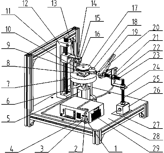
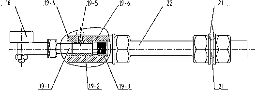
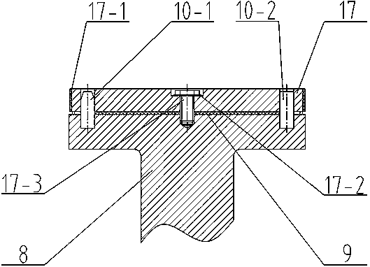
[0027] Such as figure 1 The shown friction and wear test device under current-carrying conditions is mainly composed of a motor 5, a pressure frame 7, a transmission shaft 8, an insulating disc 9, an insulating positioning pin 10, a linear guide rail 12, a connecting cover plate 15, a nylon block 14, Sample fixture 13, cylindrical pin 16, test disc 17, conductive foam 17-1, bearing 18, buffer 19, wire clip 20, insulating sleeve 22, horizontal screw 23, right-angle frame 24, vertical screw 25, Magnetic base 26, insulating plate 27, base plate 28 and DC voltage stabilizer 29 etc. constitute. Described magnetic base 26 is adsorbed on the base plate 28 by magnetic force and separates insulating plate 27, utilizes the switch control adsorption of magnetic base 26; Connect below, wherein the horizontal screw rod 23 is connected with the left end face of the right-angle frame 24, and the insulating sleeve 22 is put into the left end hole of the right-angle frame 24 before the horizo...
specific Embodiment approach 2
[0029] The difference from Embodiment 1 is that there is no need to paste conductive foam (17-1) on the side of the experimental disc (17), so that the bearing (18) is in direct contact with the surface of the experimental disc (17). This structure is used for rolling loads. Flow friction test.
PUM
Abstract
The invention discloses a frictional wear test device under a current-carrying condition. The frictional wear test device mainly comprises a motor, a pressure-bearing frame, an insulating disc, an insulating positioning pin, a linear guide rail, a sample clamp, a cylindrical pin, an experimental disc, a bearing, a buffer, a wire lapping clamp, an insulating sleeve, an insulating spacer, a horizontal screw rod, a right-angle frame, a vertical screw rod, a magnetic seat, an insulating plate, a bottom plate, a DC voltage stabilizer and the like. Rolling friction exists between the bearing and theexperimental disc in the device, sliding friction exists between the cylindrical pin and the experimental disc, and sliding and rolling current-carrying friction abrasion tests can be carried out. Through the multi-layer insulation design, the experiment device is safer; full-time current carrying is realized through the buffer, so that the stability and the operability of related friction and wear tests are greatly improved; when a sliding current-carrying frictional wear test is carried out, the reliability and the low noise of the test process are improved through the conductive foam adhered to the test disc; the test device and the sample are simplified and reduced as much as possible, and the green economy of the test and the easy installation of the device are improved.
Description
technical field [0001] The invention relates to the field of experimental testing equipment, in particular to a friction and wear test device under current-carrying conditions. Background technique [0002] Current-carrying friction and wear refers to the wear and tear caused by the coupling of multiple factors such as the transmission and load of the force that the current friction pair participates in. Under the coupling effect of mechanical wear and current wear caused by the coupling of factors such as current and friction and wear, the friction and wear characteristics will become more complicated, and the service life and stability of related equipment with current-carrying friction pairs have become a research hotspot. . [0003] Current-carrying friction and wear involves many fields, such as the more common motor brush systems, wind power generation systems in the field of environmental protection power generation, typical return systems in rail transit systems, an...
Claims
Application Information
Patent Timeline
Application Date:The date an application was filed.
Publication Date:The date a patent or application was officially published.
First Publication Date:The earliest publication date of a patent with the same application number.
Issue Date:Publication date of the patent grant document.
PCT Entry Date:The Entry date of PCT National Phase.
Estimated Expiry Date:The statutory expiry date of a patent right according to the Patent Law, and it is the longest term of protection that the patent right can achieve without the termination of the patent right due to other reasons(Term extension factor has been taken into account ).
Invalid Date:Actual expiry date is based on effective date or publication date of legal transaction data of invalid patent.