Method and device for detecting mutual inductance parameters of coupling loop in wireless power transmission system

A technology of wireless energy transmission and coupling loop, which is applied in measuring devices, transportation and packaging, measuring electricity, etc., can solve the problems of poor stability of transmission efficiency and unstable transmission efficiency, etc., and achieve direct and accurate changes, fast detection, The effect of improving stability

Active Publication Date: 2022-07-08
CHINA CREC RAILWAY ELECTRIFICATION BUREAU GRP
View PDF11 Cites 1 Cited by
  • Summary
  • Abstract
  • Description
  • Claims
  • Application Information

AI Technical Summary

Problems solved by technology

[0004] However, these two methods are indirect solutions to the problem of unstable transmission efficiency, and have a poor effect on the stability of transmission efficiency.

Method used


Image

  • Method and device for detecting mutual inductance parameters of coupling loop in wireless power transmission system
  • Method and device for detecting mutual inductance parameters of coupling loop in wireless power transmission system
  • Method and device for detecting mutual inductance parameters of coupling loop in wireless power transmission system

Examples


Embodiment Construction

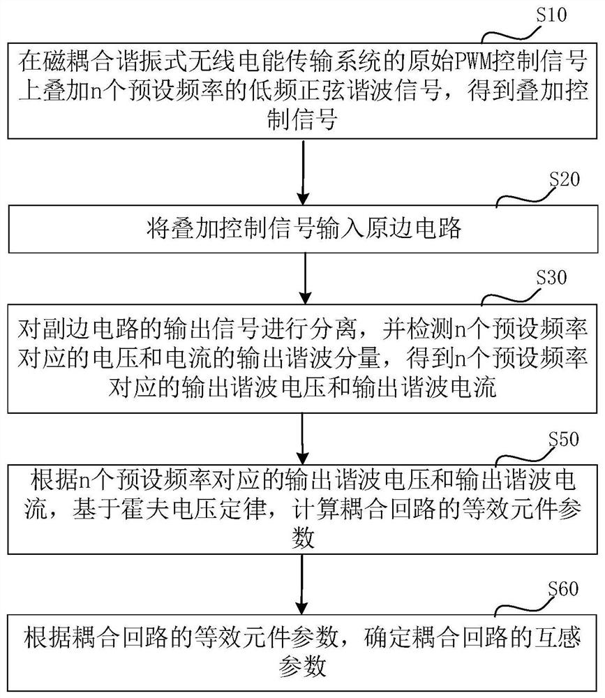
[0055] In order to make the purpose, technical solutions and advantages of the present application more clearly understood, the present application will be described in further detail below with reference to the accompanying drawings and embodiments. It should be understood that the specific embodiments described herein are only used to explain the present application, but not to limit the present application.

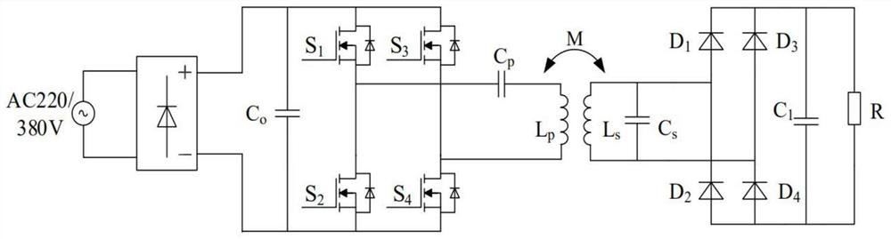
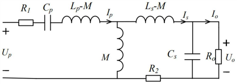
[0056] The method for detecting the mutual inductance of the coupling loop of the wireless power transmission system provided by the present application is used to detect the mutual inductance of the coupling loop of the magnetic coupling resonance wireless power transmission system. The coupling loop of the magnetically coupled resonant wireless power transmission system includes a primary side circuit and a secondary side circuit. In the embodiment of the present application, the magnetically coupled resonant wireless power transmission system may be a primary side s...


PUM


Abstract

The present application relates to a method and device for detecting mutual inductance parameters of a coupling loop of a wireless power transmission system. The method includes: superimposing n low-frequency sinusoidal harmonic signals of preset frequencies on the original PWM control signal of the magnetic coupling resonance wireless power transmission system to obtain the superimposed control signal; inputting the superimposed control signal into the primary side circuit; The output signal of the circuit is separated, and the output harmonic components of the voltage and current corresponding to the n preset frequencies are detected to obtain the output harmonic voltage and output harmonic current corresponding to the n preset frequencies; The output harmonic voltage and output harmonic current are calculated based on Hough's voltage law, and the equivalent element parameters of the coupling loop are calculated; according to the equivalent element parameters of the coupling loop, the mutual inductance parameters of the coupling loop are determined. The method can detect the mutual inductance parameters of the coupling loop.

Description

technical field [0001] The present application relates to the technical field of wireless power transmission, and in particular, to a method and device for detecting a mutual inductance parameter of a coupling loop of a wireless power transmission system. Background technique [0002] During the operation of the wireless power transmission system, due to the battery characteristics and the relative position deviation of the coupling coil, the load and mutual inductance parameters will change in real time during the charging process. Changes in load and mutual inductance parameters will lead to changes in coupling parameters and energy transfer characteristics, affecting the resonant process of the converter, thereby changing the operating conditions and transmission efficiency, making the transmission efficiency unstable. [0003] In the traditional technology, two methods are generally used to solve the problem of unstable transmission efficiency: the first is the parameter...

Claims


Application Information

Patent Timeline
Patent Type & Authority Patents(China)
IPC IPC(8): G01R31/00G01R19/00
CPCG01R31/00G01R19/00Y02T90/14
Inventor 林云志向伟刘远略赖一雄
Owner CHINA CREC RAILWAY ELECTRIFICATION BUREAU GRP
Why Eureka
Try Eureka