Electronic device and manufacturing method thereof

A technology of electronic devices and batteries, which is applied in the field of electronic equipment, can solve problems such as increasing battery weight, battery deformation, and reducing battery capacity, and achieves the effects of simple sealing structure, reduced space occupation, and good sealing effect

Pending Publication Date: 2020-07-14
EVE ENERGY CO LTD
View PDF0 Cites 26 Cited by
  • Summary
  • Abstract
  • Description
  • Claims
  • Application Information

AI Technical Summary

Problems solved by technology

The prior art has the following defects: 1. The length of the second surrounding wall of the cap needs to be controlled. If the size is too short, it will cause poor sealing during sealing, and if it is too long, it will increase the weight of the battery; 2. For larger size For the battery, the extrusion sealing method is unreliable and prone to liquid leakage; 3. The extrusion sealing method makes the internal space of the battery occupied by the deformed structure after extrusion, reducing the battery capacity

Method used


Image

  • Electronic device and manufacturing method thereof
  • Electronic device and manufacturing method thereof
  • Electronic device and manufacturing method thereof

Examples


Embodiment Construction

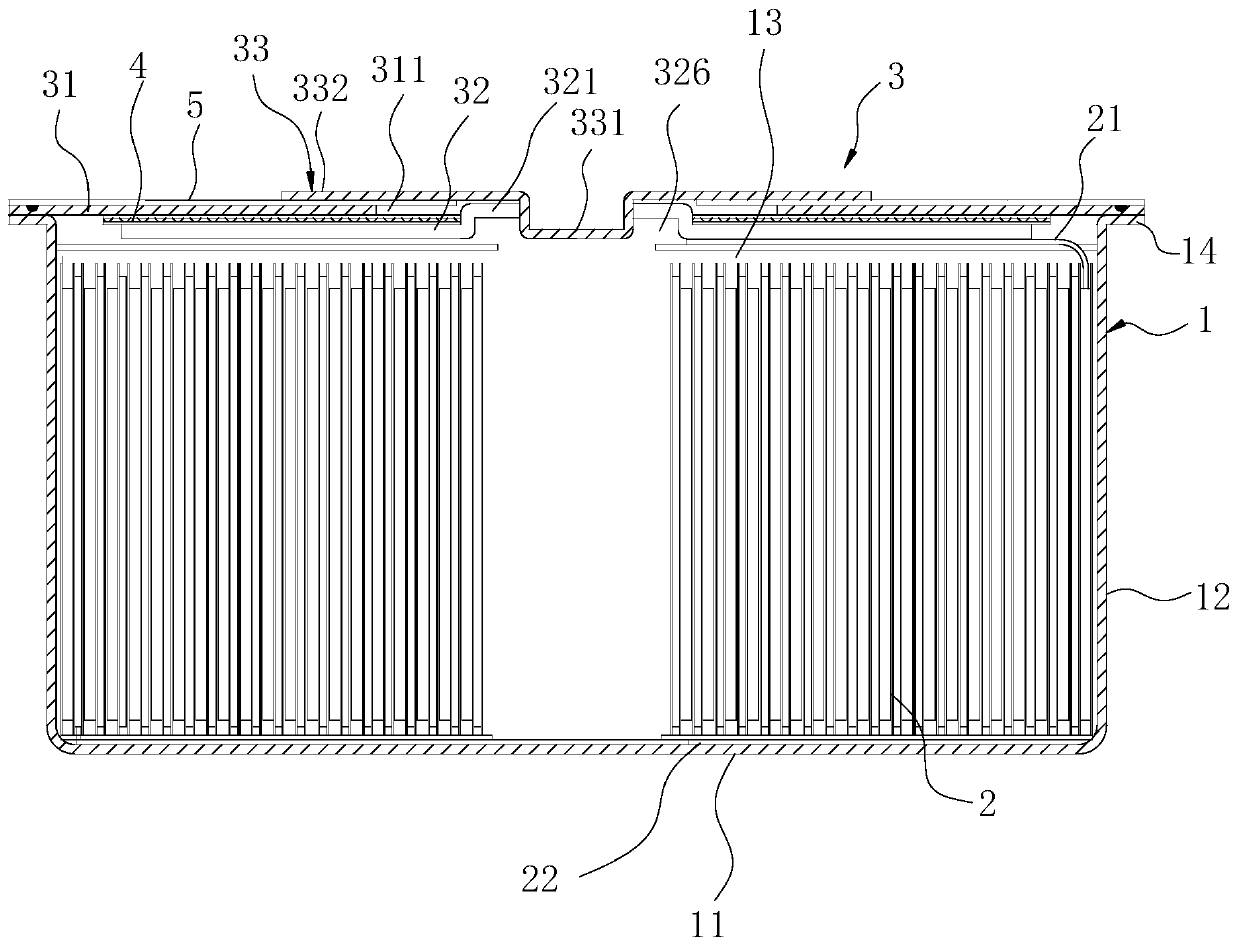
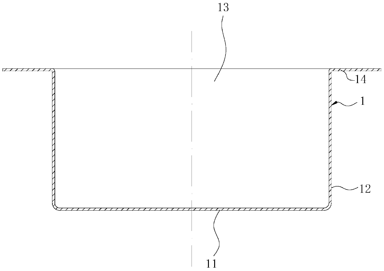
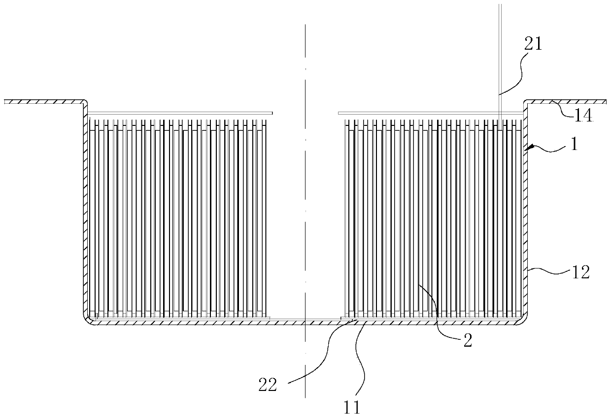
[0039] In order to make the technical problems solved by the present invention, the technical solutions adopted and the technical effects achieved clearer, the technical solutions of the embodiments of the present invention will be further described in detail below in conjunction with the accompanying drawings. Obviously, the described embodiments are only the technical solutions of the present invention. Some, but not all, embodiments. Based on the embodiments of the present invention, all other embodiments obtained by those skilled in the art without creative efforts fall within the protection scope of the present invention.

[0040]In the description of the present invention, unless otherwise clearly specified and limited, the terms "connected", "connected" and "fixed" should be understood in a broad sense, for example, it can be a fixed connection, a detachable connection, or an integrated ; It can be a mechanical connection or an electrical connection; it can be a direct ...


PUM

PropertyMeasurementUnit
glass transition temperatureaaaaaaaaaa
tensile strengthaaaaaaaaaa
thicknessaaaaaaaaaa

Abstract

The invention discloses an electronic device and a manufacturing method thereof. The electronic device comprises a shell, a battery cell and a sealing plate assembly; the shell comprises a base plateand a surrounding wall; an accommodating cavity for accommodating the battery cell is formed between the surrounding wall and the substrate; an opening communicated with the accommodating cavity is formed in the end, away from the substrate, of the surrounding wall; the sealing plate assembly is used for sealing opening; the sealing plate assembly comprises a body; the body is welded with the shell and blocks the opening; the body is provided with a first side face close to the accommodating cavity and a second side face opposite to the first side face; the first side face is in insulated connection with an electrode guide plate; the electrode guide plate is connected with one tab of the battery cell; a first protruding part is arranged on the side, close to the first side face, of the electrode guide plate in a protruding mode; a liquid injection hole is formed in the first protruding part in a penetrating mode; a first through hole allowing the first protruding part to pass through is formed in the body; the second side face is in insulation connection with a conductive sealing cover; and a second protruding part is arranged on the sealing cover in a protruding mode and insertedinto the liquid injection hole to block the liquid injection hole. The electronic device is simple in structure and reliable in sealing.

Description

technical field [0001] The invention relates to the technical field of electronic equipment, in particular to an electronic device and a manufacturing method thereof. Background technique [0002] At present, batteries with a hard shell structure are usually sealed by extrusion. The battery includes a bottom case, a cap and a battery cell. Both the bottom case and the cap are of a shell structure with one end sealed and one end open. The first surrounding wall on one side, the cap includes a top plate and a second surrounding wall ring arranged on one side of the top plate. When the bottom shell and the cap are assembled, the second surrounding wall is sleeved outside the first surrounding wall, and between the two surrounding walls A sealing ring is provided. When assembling, put the battery cell in the bottom case, put a sealing ring on the first wall of the bottom case, and then assemble the cap with the bottom case after injecting liquid, and squeeze the second wall and...

Claims


Application Information

Patent Timeline
Patent Type & Authority Applications(China)
IPC IPC(8): H01M2/02H01M2/04H01M2/26H01M2/36H01M10/04
CPCH01M10/0431H01M50/10H01M50/166H01M50/531H01M50/60Y02E60/10Y02P70/50
Inventor 刘亮亮祝媛袁中直刘建华刘金成
Owner EVE ENERGY CO LTD
Why Eureka
Try Eureka