
Grafting machine

A technology of grafting machine and guide rail, which is applied in grafting and other directions, and can solve problems such as complex overall structure, poor bonding between scion and rootstock, and connection errors

Active Publication Date: 2020-07-17
UNIV OF JINAN
View PDF9 Cites 4 Cited by
  • Summary
  • Abstract
  • Description
  • Claims
  • Application Information

AI Technical Summary

Problems solved by technology

[0003] As mentioned above, there needs to be a close connection between the rootstock and the scion to ensure that the scion can form a living. At present, the interface between the rootstock and the scion is mostly a V-shaped interface. This kind of V-shaped interface is easy to make. In this type of V-shaped interface There are two contact surfaces between the rootstock and the scion, and the two contact surfaces are V-shaped. When artificially grafting, there are not too many requirements for the V-shaped V angle, which is mainly 6-30 degrees to obtain a relatively high survival rate. Therefore, the V angle is generally less than 20 degrees during manual grafting, while the V angle adapted to the grafting machine is mostly 60-70 degrees, the contact surface is relatively small, the clamping effect of the rootstock on the scion is relatively small, and the scion’s Relatively poor bonding firmness
[0004] Chinese patent document CN110383995A discloses a kind of grafting equipment, and it constructs grafting equipment in the mode of streamlined operation, and the scion cutting device that it comprises and rootstock cutting device are arranged on the vertical direction, and two cutting devices are mutually driven There is no interference with the form of movement. In other words, it needs to be equipped with two sets of cutting devices. The synchronization of the movement is not good, and the shape of the incision produced by cutting is not easy to match. Fault-tolerant, but because the flow is equivalent to limiting the scion to move horizontally first, then lift vertically, then move horizontally, and finally align vertically with the rootstock delivered, a series of connection errors will occur, and the alignment accuracy is not easy to guarantee , prone to misalignment between incisions
In view of this, the incision form is relatively simple to reduce the poor quality of grafting alignment caused by movement interference. The incision is an oblique incision, and there is only one inclined plane between the scion and the rootstock. Obviously, in the same binding situation However, the bonding firmness between the scion and the rootstock is relatively poor, and the overall incision contact area is small, and the survival rate of the scion needs to be verified.
[0005] Chinese patent document CN110235625A discloses a plant grafting device and a grafting method, which provides a fixed rootstock holder and a vertical guide post fixedly installed on the rootstock holder, the scion holder is installed on the guide post through a slider, and the guide There is also a cutting device slidingly installed on the column. Relatively speaking, it is relatively difficult to clamp the rootstock and scion in the vertical state, especially for the objects located below, and the clamping space will be relatively greatly affected
Specifically in the Chinese patent document CN110235625A, there is a mounting plate in the middle of the track, and a cutting device is installed on the mounting plate. The cutting device includes two mounting plates, and a cutting device and an auxiliary cutting device are installed on the two mounting plates. Complicated structure
In order to meet the alignment after cutting, the incision is a V-shaped incision. As mentioned above, compared with the oblique incision, the V-shaped incision has an additional joint surface, but since the joint surfaces are all planes and are affected by the grafting machine Due to the inherent limitations of machine cutting, the angle of the V opening is relatively large, usually greater than 60 degrees, and the bonding firmness between the scion and the rootstock is relatively poor

Method used

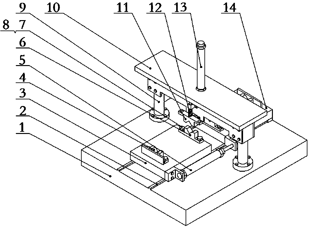
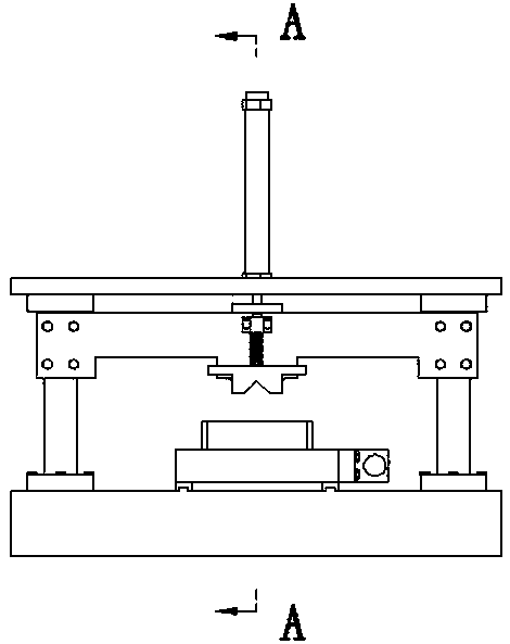
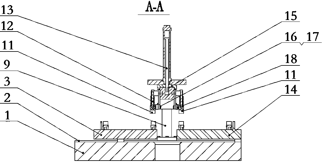

Image

  • Grafting machine
  • Grafting machine
  • Grafting machine

Examples


Embodiment Construction

[0036] The traditional grafting machine has many main actions, usually no less than four, many links, many accumulated errors, and many fault points, and the connection between each action and the next action often has a connection error. However, in the embodiment of the present invention, the grafting machine mainly has two actions, that is, vertical cutting and horizontal splicing. Among them, the splicing in the horizontal direction is different from the traditional vertical splicing, and the rootstock Z1 and the scion J1 are opposite in the horizontal direction. The splicing depends on the positioning accuracy in the early stage. The splicing objects do not need to be transferred, and the splicing accuracy is easy to guarantee. . This is the basic purpose of this embodiment.

[0037] In order to realize the above-mentioned basic purpose and the understanding and realization of the present invention, in the following embodiments, it is expanded layer by layer Figure 1~3...


PUM

PropertyMeasurementUnit
Central angleaaaaaaaaaa

Abstract

According to the grafting machine, the cutting direction of the grafting machine is changed into the vertical cutting direction, and the cut part of an object and the remaining part do not interfere with each other in the falling direction. The cutting can form a relatively complex incision under the action condition, and particularly, the corresponding cutting edge is provided with an arc-shapedmain edge with the central angle larger than 180 degrees and smaller than or equal to 190 degrees, arc-shaped transition edges continuously connected to the two ends of the arc-shaped main edge in a guiding mode to extend outwards, and straight auxiliary edges connected to the tail ends of the arc-shaped transition edges. Wherein an incision formed by the arc-shaped main blade is mainly used for generating an additional forceps clip, the arc-shaped transition blade roughly forms a flaring structure which is similar to a traditional V-shaped incision and facilitates insertion of a scion, the straight auxiliary blade has better adaptability to the specification and size of a plant, and the whole incision not only is larger in area, but also is provided with a forceps clip part and better incombination firmness. The survival of the scions is favorably ensured.

Description

technical field [0001] The invention relates to a grafting machine. Background technique [0002] Grafting is a kind of traditional asexual vegetative reproduction. During grafting, scion and rootstock should be closely combined to ensure that the scion can survive. Among them, the scion refers to the branches or buds taken from the stable female parent of fruits and vegetables or other crops. The branches or buds taken from the female parent are called Xinshao (which are divided into spring, summer and autumn according to different seasons). There can be 4~5 times a year in the tropics, and the new ones can be used as scions to be grafted after aging. Rootstock refers to the plant that bears the scion when grafting and propagating. The rootstock can be the whole plant, or the root segment or branch segment on the plant. Most of the rootstocks and scions that are suitable for machine grafting need to be grafted in batches, and the shape consistency of rootstock and scion i...

Claims


Application Information

Patent Timeline
IPC IPC(8): A01G2/35
CPCA01G2/35
Inventor 李金坤王守仁杨丽颖温道胜王高琦时晓宇薛成龙杨冰冰郭宇吴戍戌王东跃
Owner UNIV OF JINAN
Learn More