oil scraper

A technology of oil scraping device and oil scraping roller, which is applied to workpiece cleaning devices, manufacturing tools, metal rolling, etc., and can solve problems such as not removing moisture from the surface of the strip steel, difficulty in scraping the oil scraping roller, and rust on the surface of the strip steel , achieve the effects of shortening the roll changing time, compact structure and improving quality

Active Publication Date: 2022-03-08
CHANGZHOU BAOLING HEAVY IND MACHINERY
View PDF10 Cites 0 Cited by
  • Summary
  • Abstract
  • Description
  • Claims
  • Application Information

AI Technical Summary

Problems solved by technology

[0004] Although the above-mentioned prior art is provided with an air knife assembly on one side of each oil scraper roller to remove the rolling oil accumulated on the oil scraper roller, the above-mentioned air knife assembly only blows and can only act on the oil scraper roller and the belt. However, during the working process of the oil scraping roller, the rolling oil is bound to adhere to the oil scraping roller. With the high-speed rotation of the oil scraping roller, a part of the rolling oil is absorbed by the centrifugal force of the oil scraping roller. It is thrown out, causing the rolling oil to splash, and the other part continues to rotate with the oil scraping roller. The oil scraping roller is difficult to scrape off and then move the rolling oil on the surface of the strip.
[0005] In addition, although the above-mentioned steel strip has been scraped by the oil scraping roller, moisture still remains on the surface of the steel strip output from the oil scraping device, that is, the above-mentioned device does not have the function of removing moisture on the surface of the strip steel, so the surface of the steel strip output In a wet state, there are still defects that make the surface of the strip rust

Method used


Image

  • oil scraper
  • oil scraper
  • oil scraper

Examples


Embodiment Construction

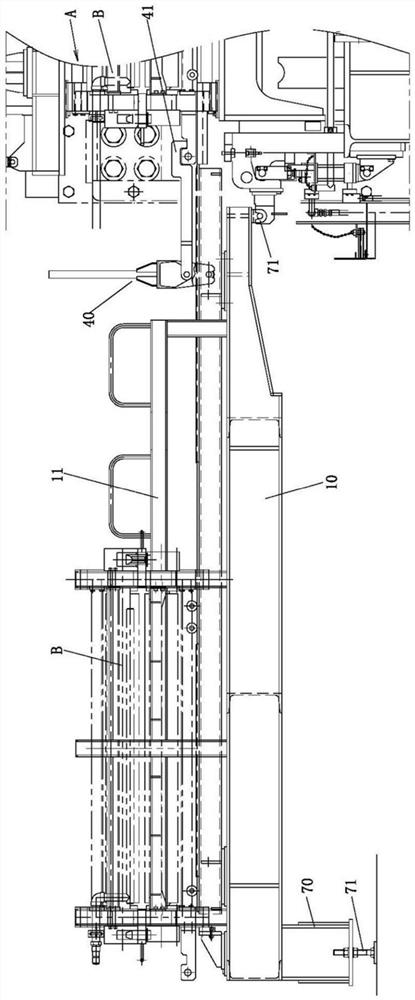
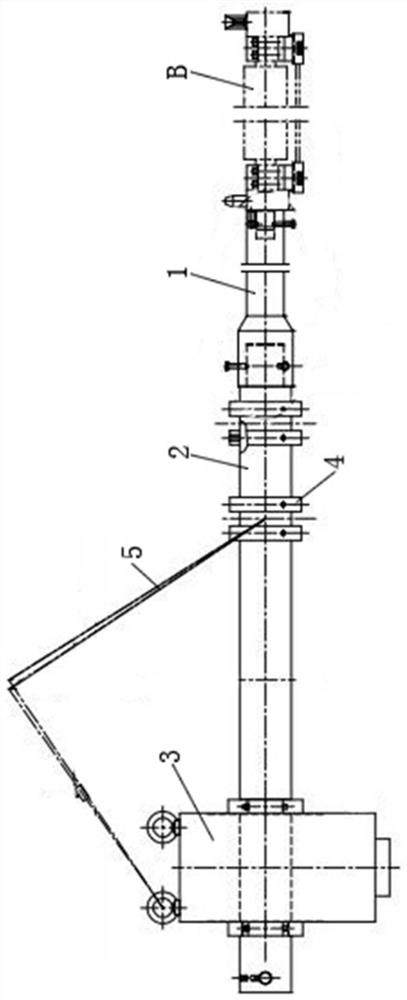
[0030] Such as figure 1 , the oil scraping and roller changing system of the present invention is made up of oil scraping device A and the roller changing device of quick replacement oil scraping roller B, and the following two major parts are described respectively below:

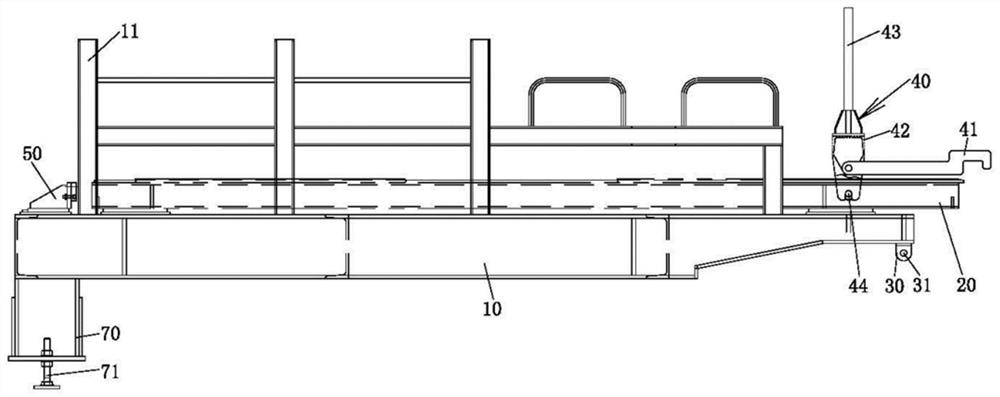
[0031] Such as figure 1 and figure 2 , the roll changing device for quickly changing the oil scraping roller B, including a roll changing frame 10, one or more roll changing tracks, a positioning part 30, and a roll changing driving mechanism 40, which will be described in detail below:

[0032] Such as figure 1 and figure 2 , since the oil scraping roller B is composed of an upper roller assembly and a lower roller assembly, and the upper roller assembly and the lower roller assembly move at the same time, therefore, the overall height of the oil scraping roller B is relatively high, thus, on the roller stand 10 The guardrail 11 is set, and the oil scraping roller B is blocked by the guardrail 11, s...


PUM


Abstract

The invention relates to an oil scraping device, which includes multiple groups of scraping rollers, an upper mounting frame, a lower mounting frame, a lifting driver, a first scraping mechanism, and a first blowing mechanism. Each group of scraping rollers consists of an upper roller assembly and a The upper roller assembly is composed of the lower roller assembly opposite to the upper roller assembly. The upper roller assembly cooperates with the upper mounting frame, the lower roller assembly cooperates with the lower mounting frame, and the lifting drive is connected with the upper mounting frame and / or the lower mounting frame. The first scraping mechanism is located on the entire scraping frame. The inlet port of the oil device, the first blowing mechanism is arranged on one side of the oil scraping roller, the first blowing mechanism includes a first pipeline and a first nozzle for gas blowing the surface of the strip, and the first nozzle is arranged on the first On the pipeline, the first purging mechanism also includes one or more second nozzles for gas purging the roller body of the oil scraping roller, and the second nozzles are connected with the first pipeline. The invention has the advantage of improving oil scraping efficiency.

Description

technical field [0001] The invention relates to the technical field of strip steel oil scraping, in particular to an oil scraping device. Background technique [0002] The rolling mill is used to roll strip steel. During the rolling process, a large amount of rolling oil needs to be sprayed for cooling, lubrication and cleaning. After the rolling is completed, if the rolling oil is not wiped clean, watermark defects will be formed on the surface of the strip steel. , If the rolling oil remains on the surface of the strip for a long time, the moisture in the rolling oil will rust the surface of the strip after a long time, forming surface rust defects, and the defective strip users cannot accept it. Therefore, the oil scraper has become an important mechanism of the rolling mill. [0003] CN203370843U discloses a novel rolling mill oil scraping mechanism, comprising an upper platform frame and a lower platform frame, and an oil scraping roller capable of rotating around its ...

Claims


Application Information

Patent Timeline
Patent Type & Authority Patents(China)
IPC IPC(8): B21B45/02B21B31/10B25B27/00
CPCB21B45/0284B21B31/10B25B27/00
Inventor 赵纪凯梅如敏董春光
Owner CHANGZHOU BAOLING HEAVY IND MACHINERY
Why Eureka
Try Eureka