Cast steel cooling wall with evenly arranged cooling water pipe grooves and processing technology thereof

A cooling water pipe and uniform arrangement technology, applied in the field of cast steel staves, can solve the problems of uneven cooling capacity of the stave surface, uneven arrangement of cooling water pipes, unsuitable blast furnace reaction equipment, etc., and achieve the same cooling contact range, Avoid uneven heat dissipation efficiency and complete and reasonable structure

Active Publication Date: 2020-07-17
MAANSHAN RUNTONG HEAVY IND TECH CO LTD
View PDF5 Cites 5 Cited by
  • Summary
  • Abstract
  • Description
  • Claims
  • Application Information

AI Technical Summary

Problems solved by technology

[0003] The cooling water pipelines inside the cooling stave of the traditional technology are unevenly arranged, resulting in uneven cooling capacity of the stave surface during the high-heat reaction process of the blast furnace, resulting in differences in the heat dissipation speed of the inner bottom surface of the blast furnace, which may As a result, the reaction substances in the blast furnace form other substances due to the temperature cooling too fast or too slow, so that the target substance cannot be obtained. At the same time, the cooling pipeline in the cooling wall is usually cooled by a single pipeline, and the efficiency of heat conduction cooling is low, which is not suitable for Blast furnace reaction equipment requiring rapid cooling

Method used


Image

  • Cast steel cooling wall with evenly arranged cooling water pipe grooves and processing technology thereof
  • Cast steel cooling wall with evenly arranged cooling water pipe grooves and processing technology thereof
  • Cast steel cooling wall with evenly arranged cooling water pipe grooves and processing technology thereof

Examples


Embodiment Construction

[0032] The technical solutions in the embodiments of the present invention will be clearly and completely described below in conjunction with the accompanying drawings in the embodiments of the present invention. Obviously, the described embodiments are only a part of the embodiments of the present invention, rather than all the embodiments. Based on the embodiments of the present invention, all other embodiments obtained by those of ordinary skill in the art without creative work shall fall within the protection scope of the present invention.

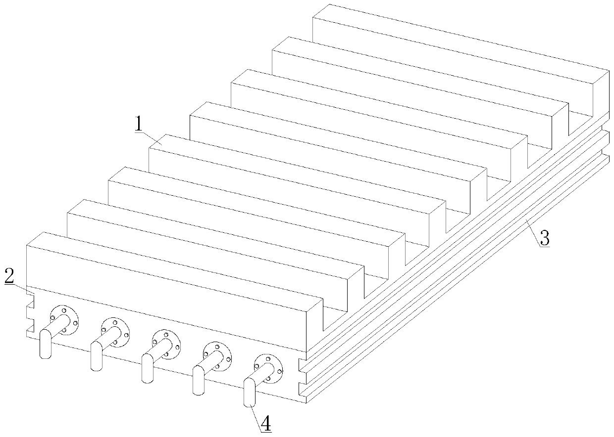
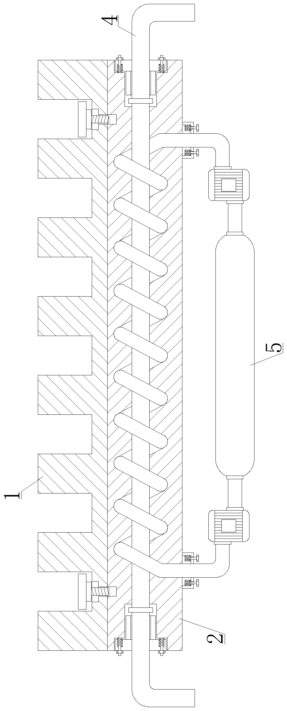
[0033] See Figure 1-2 , The cast steel cooling wall with evenly arranged cooling water pipe grooves, including the heat conduction plate 1, the heat dissipation plate 2, the embedded slide groove 3, the outer pipe plug 4 and the condensing circulation mechanism 5. The heat dissipation plate 2 is installed on the lower side of the heat conduction plate 1, and the heat dissipation plate 2 Mainly used for the overall heat dissipation of the...


PUM


Abstract

The invention discloses a cast steel cooling wall with evenly arranged cooling water pipe grooves and a processing technology thereof. The cast steel cooling wall with the evenly arranged cooling water pipe grooves comprises a heat conduction plate, a heat dissipation plate, embedded sliding chutes, outer pipe plugs and a condensation and circulation mechanism, wherein heat conduction straight pipes are evenly arranged inside the heat dissipation plate; spiral heat dissipation pipes are wound on the outer sides of the heat conduction straight pipes; based on the cooling of the ordinary heat conduction straight pipes, the spiral heat dissipation pipes are used for simultaneously exchanging the temperature of the heat conduction straight pipes and the heat dissipation plate; cooling water after heat exchange is conveyed to a long cooling pipe through a circulating water pump; and cooling liquid in the outer wall of the long cooling pipe is used for cooling, and then is conveyed into thespiral heat dissipation pipes for recycling by the circulating water pump. The pipelines in the cooling wall are arranged neatly and evenly, and have the same cooling contact range everywhere in a blast furnace, so that the uneven heat dissipation efficiency in the blast furnace is avoided; and the cast steel cooling wall has high cooling efficiency everywhere, can be applied to various blast furnace reaction equipment and has relatively strong compatibility.

Description

Technical field [0001] The invention relates to the technical field of cast steel cooling staves, in particular to a cast steel cooling stave with evenly arranged cooling water pipe grooves and a processing technology thereof. Background technique [0002] Cooling stave is a type of cooler commonly used in blast furnaces at present. According to its material, it is divided into cast iron stave, copper stave, steel stave and steel-copper composite stave, etc. The blast furnace is mainly transferred out of the blast furnace through surface cooling. The heat of the blast furnace is smoothly discharged to avoid the high temperature heat flow directly reaching the furnace shell. The cooling stave is installed between the brick lining and the furnace shell to achieve this effect. The modern blast furnace adopts the full cooling stave structure, and the furnace shell from the bottom to the throat The cooling wall or water wall is installed to form a fully cooled furnace body structure. ...

Claims


Application Information

Patent Timeline
Patent Type & Authority Applications(China)
IPC IPC(8): C21B7/10B22D19/00
CPCB22D19/00C21B7/10
Inventor 李以则张登义朱童斌谢能刚
Owner MAANSHAN RUNTONG HEAVY IND TECH CO LTD
Why Eureka
Try Eureka