Laser radar calibration method and device, storage medium and self-moving equipment

A technology of laser radar and calibration method, which is applied in the direction of radio wave measurement system, instrument, etc., can solve the problems of lack of accuracy and unfavorable data fusion processing, etc.

Active Publication Date: 2020-07-17
LEISHEN INTELLIGENT SYST CO LTD
View PDF7 Cites 10 Cited by
  • Summary
  • Abstract
  • Description
  • Claims
  • Application Information

AI Technical Summary

Problems solved by technology

At present, compared with the external parameter calibration data of self-mobile equipment, there are very few publicly available lidar external parameter calibration data.

Method used


Image

  • Laser radar calibration method and device, storage medium and self-moving equipment
  • Laser radar calibration method and device, storage medium and self-moving equipment
  • Laser radar calibration method and device, storage medium and self-moving equipment

Examples


Embodiment 1

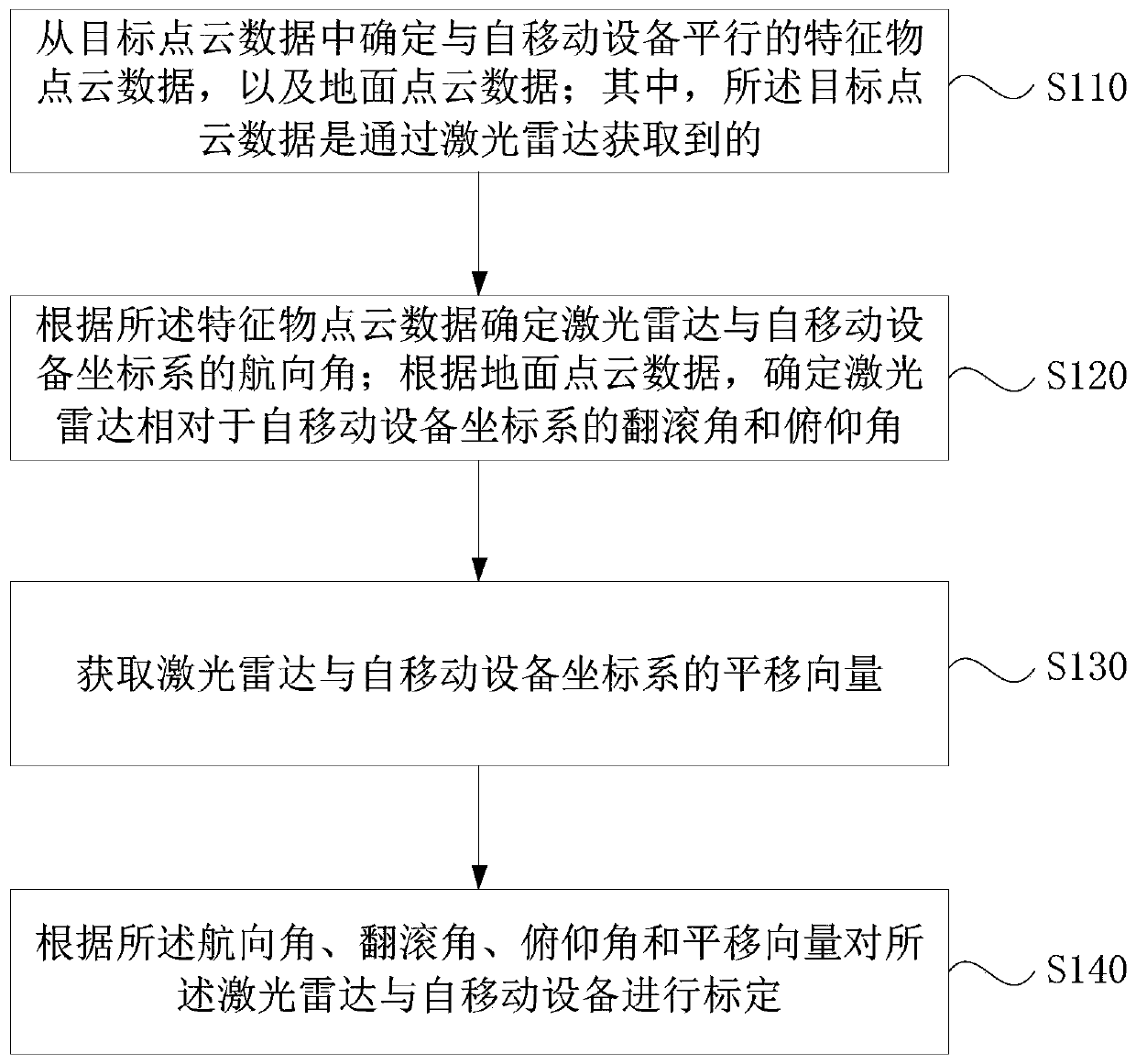
[0052] figure 1 It is a flow chart of the laser radar calibration method provided in Embodiment 1 of the present application. This embodiment is applicable to the case of calibrating the laser radar based on the coordinate system of the mobile device. This method can be implemented by the laser radar provided in the embodiment of the present application. The calibration device operates, and the device can be implemented by software and / or hardware, and can be integrated into electronic devices such as smart terminals.

[0053] Such as figure 1 As shown, the calibration method of the lidar includes:

[0054]S110. Determine feature point cloud data parallel to the self-mobile device and ground point cloud data from the target point cloud data; wherein, the target point cloud data is obtained through a laser radar.

[0055] Wherein, the self-mobile device may be a mobile device such as a vehicle or a robot. The target point cloud data can be one or more frames of point cloud d...

Embodiment 2

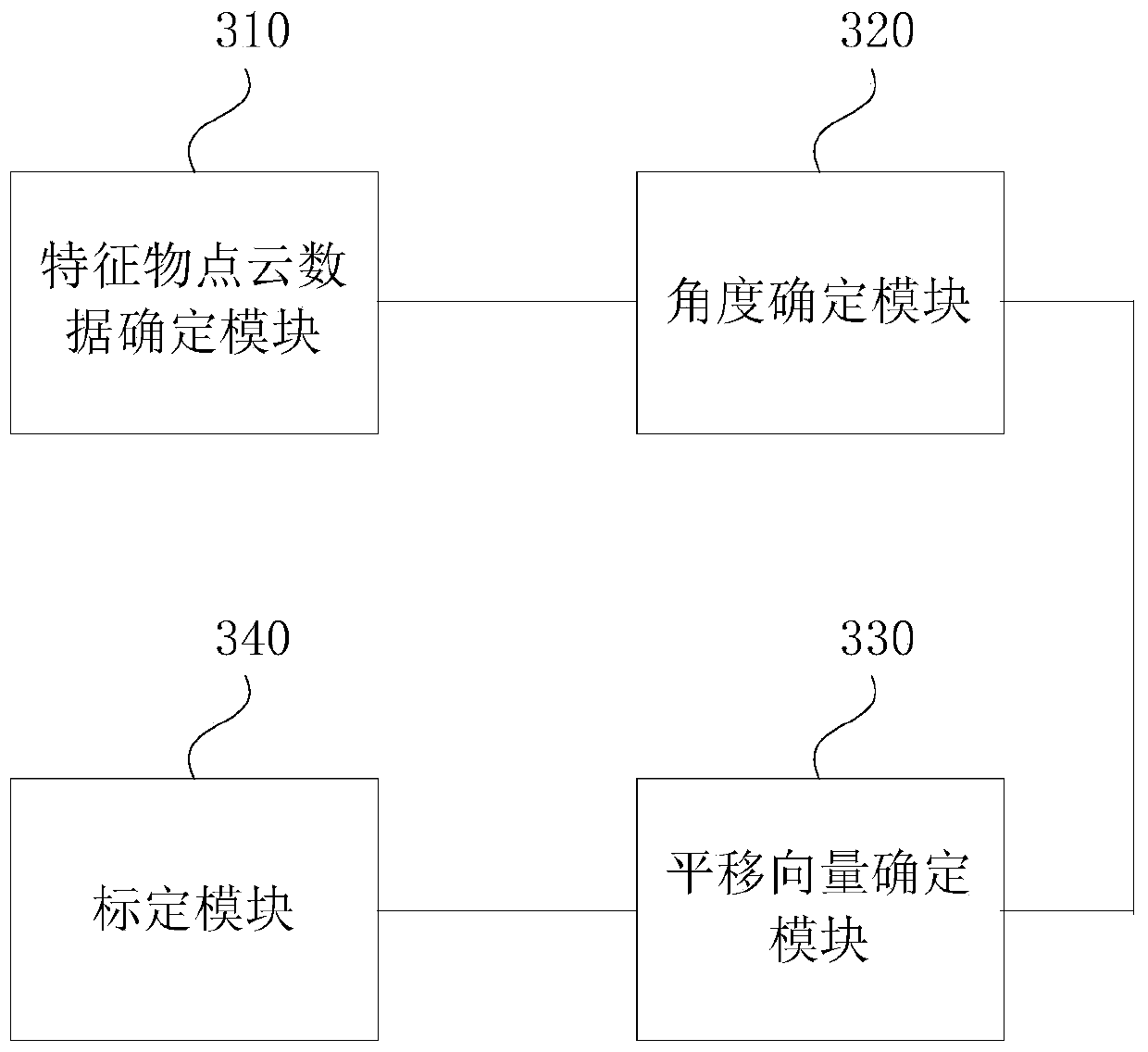
[0090] image 3 It is a schematic structural diagram of the lidar calibration device provided in Embodiment 2 of the present application. Such as image 3 As shown, the calibration device of the lidar includes:

[0091] The feature point cloud data determination module 310 is used to determine from the target point cloud data the feature point cloud data parallel to the self-mobile device, and the ground point cloud data; wherein, the target point cloud data is acquired by laser radar of;

[0092] The angle determination module 320 is used to determine the heading angle of the laser radar and the coordinate system of the mobile device according to the feature point cloud data; and determine the roll angle and pitch of the laser radar relative to the coordinate system of the mobile device according to the ground point cloud data horn;

[0093] A translation vector determination module 330, configured to obtain the translation vector of the lidar and the coordinate system of...

Embodiment 3

[0103] The embodiment of the present application also provides a storage medium containing computer-executable instructions, the computer-executable instructions are used to run a laser radar calibration method when executed by a computer processor, the method comprising:

[0104] Determining feature point cloud data and ground point cloud data parallel to the mobile device from the target point cloud data; wherein, the target point cloud data is obtained by laser radar;

[0105] Determine the heading angle of the laser radar and the coordinate system of the mobile device according to the feature point cloud data; and determine the roll angle and pitch angle of the laser radar relative to the coordinate system of the mobile device according to the ground point cloud data;

[0106] Obtain the translation vector of the lidar and the coordinate system of the mobile device;

[0107] The lidar and the mobile device are calibrated according to the heading angle, roll angle, pitch an...


PUM


Abstract

The embodiment of the invention discloses a laser radar calibration method and device, a storage medium and self-moving equipment. The method comprises the following steps: determining feature objectpoint cloud data parallel to the self-moving equipment and ground point cloud data from target point cloud data, wherein the target point cloud data is obtained through a laser radar; determining a course angle between a laser radar and a self-moving equipment coordinate system according to the feature object point cloud data; determining a roll angle and a pitch angle of the laser radar relativeto the coordinate system of the self-moving equipment according to the ground point cloud data; obtaining a translation vector of a laser radar and a self-moving equipment coordinate system; and calibrating the laser radar and the self-moving equipment according to the course angle, the roll angle, the pitch angle and the translation vector. By operating the technical scheme provided by the invention, the laser radar can be automatically calibrated, and the accuracy of the calibration result is high.

Description

technical field [0001] The embodiments of the present application relate to the technical field of laser radar, and in particular to a laser radar calibration method, device, storage medium, and self-moving equipment. Background technique [0002] With the rapid development of science and technology, the development of intelligent driving technology is in full swing. Almost all intelligent driving car manufacturers and models are using lidar as a main sensor device. Currently, autonomous driving is in a state of constant development. [0003] First of all, in automatic driving, a self-driving car will install many sensors on the car, such as cameras, lidar, millimeter-wave radar and other sensors. Each sensor has its own coordinate system, that is, all the data generated by the sensor is based on the sensor's own coordinate system. However, a self-driving car will have many sensors installed on it. In order to facilitate algorithm research and testing, it is necessary to c...

Claims


Application Information

Patent Timeline
IPC IPC(8): G01S7/497
CPCG01S7/497Y02A90/10
Inventor 胡小波喻佳澜
Owner LEISHEN INTELLIGENT SYST CO LTD
Why Eureka
Try Eureka