Retired battery module adopting flexible connection protection
A battery module, flexible connection technology, applied in battery circuit devices, arrangement of multiple synchronous batteries, secondary battery repair/maintenance, etc., can solve the lack of overvoltage and overcurrent protection functions, no uniform charging control, circuit Complicated structure and other problems, to achieve the effect of solving the problem of flexible connection, sensitive circuit response, and simple circuit structure
- Summary
- Abstract
- Description
- Claims
- Application Information
AI Technical Summary
Problems solved by technology
Method used
Image

Examples
Embodiment 1
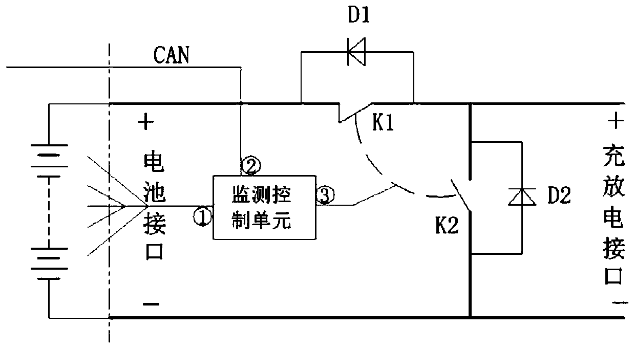
[0043] Example 1, see figure 1 , The flexible connection protection device for single decommissioned battery modules includes: charge and discharge switch (K1), charge diode (D1), bypass switch (K2), bypass diode (D2) and monitoring control unit, charge and discharge switch (K1) There should be a mechanical or logical interlock with the bypass switch (K2). Among them, one end of the charging and discharging switch (K1) is connected to the "+" of the battery interface, and the other end is connected to the "+" of the charging and discharging interface to realize the charging and discharging of the battery module; one end of the bypass switch (K2) is connected to the charging and discharging interface. The "+" of the charging and discharging interface is connected to the other end, and the battery module is bypassed; the anode of the charging diode (D1) is connected to the "+" of the charging and discharging interface, and the cathode is connected to the "-" of the battery inter...
Embodiment 2
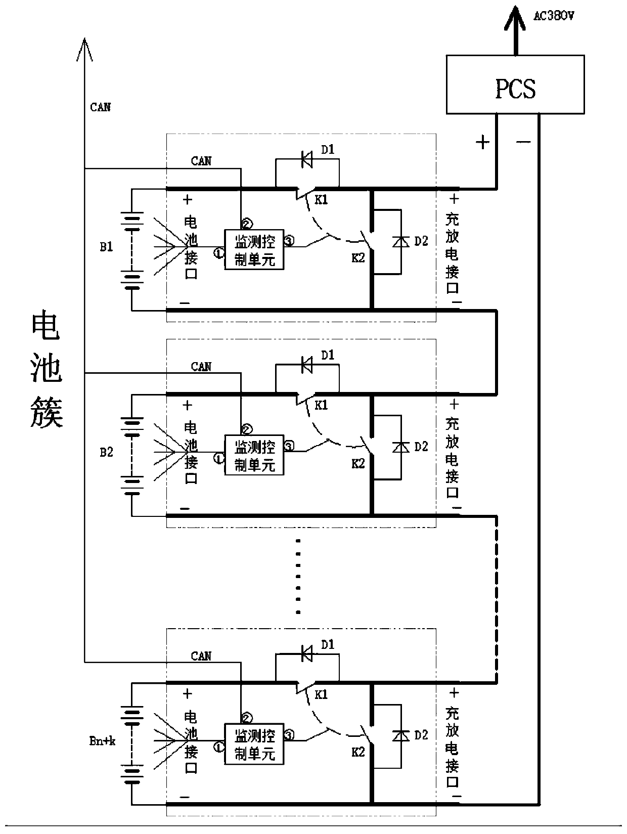
[0070] Embodiment 2, continue to refer to as figure 2 As shown, before charging (discharging) starts, the battery cluster control management unit (that is, the master control device) selects n batteries with smaller (larger) terminal voltages among n+k battery modules according to the DC bus voltage The module is put into operation, and the other k battery modules exit the bypass. After such selection, the terminal voltages of the m battery clusters are the same (within a set error range, for example, ΔU=1.0V). Then each battery cluster is connected to the DC bus in turn to start charging (discharging). Among them, n battery modules are the necessary quantity to establish the DC bus voltage, and k battery modules are redundant
[0071] Set the rotation interval to ΔT (for example, 10min), and every time a ΔT is experienced, exit the battery module with the highest (small) terminal voltage in the charging (discharging) state, and put into k bypass states with the minimum (la...
Embodiment 3
[0079] Estimation of battery module and single SOC, SOH
[0080] This battery architecture provides the conditions and means for estimating the SOC and SOH of battery modules and monomers by using the battery terminal voltage after standing still. Combined with other methods such as charge accumulation method, it can more accurately estimate the SOC and SOH of battery modules and monomers. The terminal voltage of the battery after standing for 30 minutes can basically reflect the state of charge of the battery and can be used to estimate SOC and SOH. During operation, the battery modules are input and withdrawn in turn. Assuming that the interval between turns is 10 minutes and the number of redundancy is 3, the resting time of the batteries exiting the bypass is 30 minutes. The greater the number of redundancy, the longer the battery module can stand still.
PUM
 Abstract
Description
Claims
Application Information
 - R&D
- Intellectual Property
- Life Sciences
- Materials
- Tech Scout
- Unparalleled Data Quality
- Higher Quality Content
- 60% Fewer Hallucinations
Browse by: Latest US Patents, China's latest patents, Technical Efficacy Thesaurus, Application Domain, Technology Topic, Popular Technical Reports.
© 2025 PatSnap. All rights reserved.Legal|Privacy policy|Modern Slavery Act Transparency Statement|Sitemap|About US| Contact US: help@patsnap.com