Separation source inverter decoupling control method based on synchronous reference coordinate system

A reference coordinate system, source inverter technology, applied in the direction of converting AC power input to DC power output, output power conversion device, electrical components, etc., can solve the problem of weakening the coupling degree of inverter input and output, low current quality, etc. problem, to achieve the effect of simple and convenient application and strong robustness

Active Publication Date: 2020-07-17
SHANGHAI UNIVERSITY OF ELECTRIC POWER
View PDF5 Cites 2 Cited by
  • Summary
  • Abstract
  • Description
  • Claims
  • Application Information

AI Technical Summary

Problems solved by technology

[0004] The present invention is aimed at the problem of low current quality caused by the instability of distributed power generation, and proposes a decoupling method based on a separate source inverter in a synchronous reference coordinate system The control method, which can realize the separate control of the AC side and the DC side, and the common mode item of the AC modulation signal is used to adjust the DC side, so that there are two additional degrees of freedom for the control parameters, and the coupling degree of the input and output of the inverter is weakened. Then realize the suppression of input current and output current oscillation, improve the dynamic and static stability of the entire inverter system, and ensure its safe and reliable operation

Method used


Image

  • Separation source inverter decoupling control method based on synchronous reference coordinate system
  • Separation source inverter decoupling control method based on synchronous reference coordinate system
  • Separation source inverter decoupling control method based on synchronous reference coordinate system

Examples


Embodiment Construction

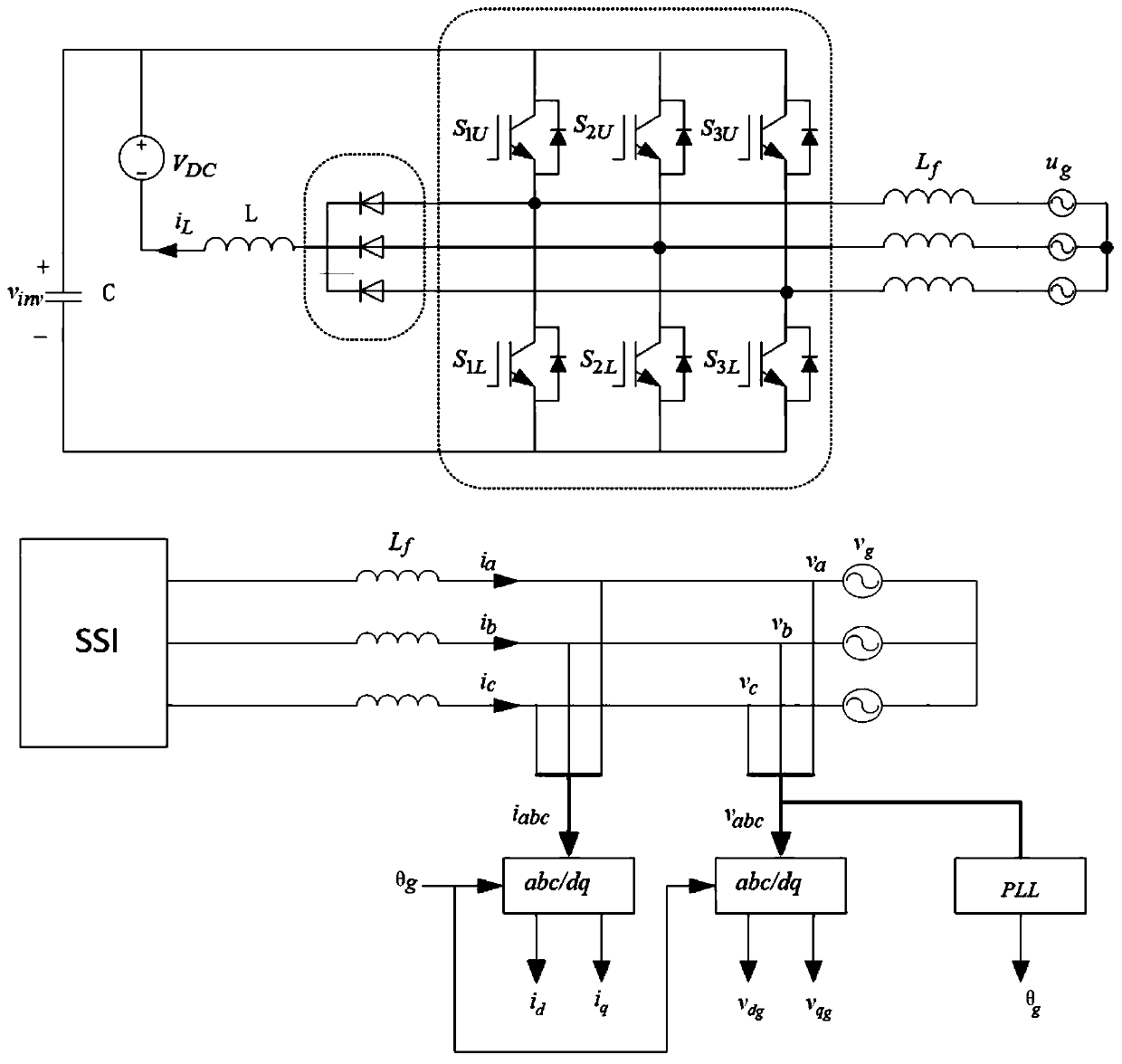
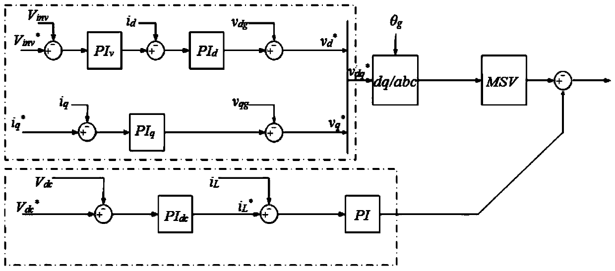
[0017] Such as figure 1 , 2 The main circuit structure diagram of the separated source inverter based on the synchronous reference coordinate system and the schematic diagram of the decoupling structure in the decoupling control method are shown. The main circuit includes a DC voltage source, a three-phase separated source inverter, an L filter, and a phase-locked loop PLL, the detection transmitter used to detect the three-phase current and voltage on the inverter side, and the three-phase current i in the three-phase static coordinate system abc and voltage v abc Converted to two-phase current i in the two-phase rotating coordinate system dq and voltage v dq The coordinate transformation unit is used to transform the coordinates of the three-phase current and three-phase voltage on the inverter side, the DC side voltage control loop, the output current control loop, the input voltage and input current double control loop, and two for A PI controller for regulating the vo...


PUM


Abstract

The invention relates to a separation source inverter decoupling control method based on a synchronous reference coordinate system. Double-loop voltage and current closed-loop control is adopted in the design of a direct-current loop controller; an outer loop is a direct-current voltage control loop, and due to the fact that the direct-current side contains an alternating-current component, a voltage loop inputs a direct-current side voltage direct-current component, and a given value of a current loop is output through PIv control; an inner loop is an input current control loop, the current iL is not affected by ripples by using a PI controller, and the direct-current side capacitor and the direct-current power supply are connected in parallel to play a role of a low-pass filter. The direct-current side and the alternating-current side are controlled separately, so that ripple waves at the direct-current side and current harmonic waves at the alternating-current side are suppressed.

Description

technical field [0001] The invention relates to an inverter control technology, in particular to a decoupling control method for a separate source inverter based on a synchronous reference coordinate system. Background technique [0002] The emergence of energy crisis, greenhouse effect and other issues has promoted the rapid development of new energy power generation technology, and new energy power generation technology has become a research hotspot. With the increasing proportion of new energy sources, the requirements for inverters are getting higher and higher. Grid-connected inverters have been widely used as the interface between distributed power generation and the grid. Since power electronic equipment cannot provide the required inertia and damping for the grid, with the continuous improvement of the penetration rate of distributed power generation, the power grid The inertia and damping are seriously insufficient, and the stability is reduced. Since the distribu...

Claims


Application Information

Patent Timeline
Patent Type & Authority Applications(China)
IPC IPC(8): H02M7/5387
CPCH02M7/5387Y02E10/56
Inventor 杨旭红陆浩宋兴龙姚凤军郝鹏飞陈阳方剑峰罗新高子轩
Owner SHANGHAI UNIVERSITY OF ELECTRIC POWER
Why Eureka
Try Eureka