A tunable true delay device and adjustment method

A resonant peak and optical modulator technology, applied in the direction of electrical components, electromagnetic wave transmission systems, transmission systems, etc., can solve the problems of size increase, adjustment difficulty, loss increase, etc., to increase the tunable range and avoid size increase big effect

Active Publication Date: 2021-07-09
UNITED MICROELECTRONICS CENT CO LTD
View PDF4 Cites 0 Cited by
  • Summary
  • Abstract
  • Description
  • Claims
  • Application Information

AI Technical Summary

Problems solved by technology

A common improvement method is to obtain a higher delay by connecting multiple microrings in series or in parallel, but there are problems such as increased loss, increased size, and difficult adjustment.

Method used


Image

  • A tunable true delay device and adjustment method
  • A tunable true delay device and adjustment method
  • A tunable true delay device and adjustment method

Examples


Embodiment 1

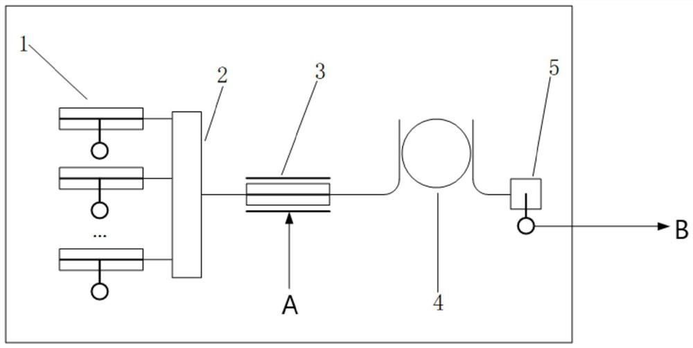
[0022] A tunable true delay device provided in this embodiment includes a multi-wavelength light source system, an optical modulator, a microring resonator, and a photodetector; the multi-wavelength light source system can selectively send and / or transmit different amounts Carrier optical signal, and the frequency or wavelength of the carrier optical signal can be adjusted and selected; in this embodiment, the multi-wavelength light source system such as figure 1 As shown, multiple lasers 1 and wavelength division multiplexers 2 are included, and each laser 1 can generate optical signals of different wavelengths in the C-band, and the emitted lasers are combined in the wavelength division multiplexer 2 through different optical paths formed by optical fiber connections. After being routed, it is output to the single sideband modulator 3; the optical signal generated by the multi-wavelength light source system can be expressed as:

[0023]

[0024] Among them, A n Indicates...


PUM


Abstract

The invention provides a tunable true delay device, which includes a multi-wavelength light source system, an optical modulator, a microring resonator and a photodetector; the output of the multi-wavelength light source system is modulated by the optical modulator and then input to the microring Resonator; the multi-wavelength light source system sends and / or transmits carrier optical signals with different wavelengths, and the frequencies of each carrier optical signal are respectively at different resonant peaks of the microring resonator or at certain interval points of resonant peak frequencies; the The optical modulator modulates the microwave signal to the carrier optical signal of each wavelength; the download end of the micro-ring resonator is optically connected with the input end of the photodetector, so as to extract and restore the signal. The invention avoids problems such as size increase and loss increase brought about by the increase in the number of microrings.

Description

technical field [0001] The invention relates to a device and an adjustment method for a tunable true time delay based on a single microring. Background technique [0002] Traditional electronically controlled phased arrays use electric phase shifters to control beamforming, which is limited by the performance of electric phase shifters, and there are problems such as beam tilt. True delay technology uses optical delay lines instead of electric phase shifters to achieve beamforming, which can effectively solve problems such as beam tilt, and has the advantages of small size, light weight, and strong anti-electromagnetic interference. The implementation method of true delay technology can be summarized as follows: first modulate the microwave signal to the optical signal through the electro-optic modulator, then input the modulated optical signal to the optical delay unit, and finally convert it into the delayed signal by the photodetector. The electric signal, which adjusts ...

Claims


Application Information

Patent Timeline
Patent Type & Authority Patents(China)
IPC IPC(8): H04B10/50
CPCH04B10/506
Inventor 冯靖崔乃迪梁宇鑫冯俊波郭进
Owner UNITED MICROELECTRONICS CENT CO LTD
Why Eureka
Try Eureka