Photoelectric fusion continuous wave radar leakage interference elimination device and method

A technology of interference elimination and photoelectric fusion, applied in the field of radar, can solve the problems of low precision of amplitude and phase control, narrow radio frequency working bandwidth, etc., and achieve the effect of wide working frequency range, large bandwidth and favorable recovery

Active Publication Date: 2020-07-17
DALIAN UNIV OF TECH
View PDF10 Cites 3 Cited by
  • Summary
  • Abstract
  • Description
  • Claims
  • Application Information

AI Technical Summary

Problems solved by technology

[0004] The present invention provides a photoelectric fusion continuous wave radar leakage interference elimination device and method, which effectively solves the limitations of the narrow radio frequency working bandwidth and low amplitude and phase control accuracy of the

Method used


Image

  • Photoelectric fusion continuous wave radar leakage interference elimination device and method
  • Photoelectric fusion continuous wave radar leakage interference elimination device and method
  • Photoelectric fusion continuous wave radar leakage interference elimination device and method

Examples


Embodiment

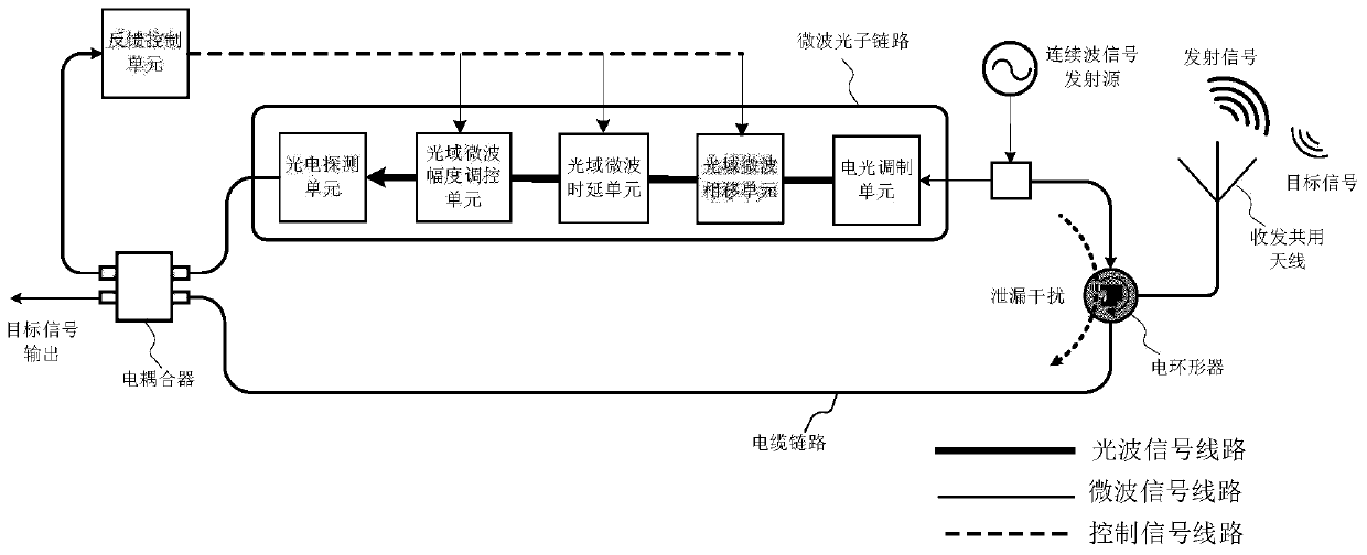
[0038] figure 1 It is a structural block diagram of the optical-electrical fusion continuous wave radar leakage interference elimination device. The low-power target signal received by the common antenna for transmitting and receiving enters the cable link of the receiver through the electric circulator, and is sent out by the continuous wave signal source, and the high-power leakage interference signal leaked through the electric circulator enters the cable link of the receiver. The signal and the leakage interference signal are jointly transmitted to the input end of the electrical coupler through the cable link.

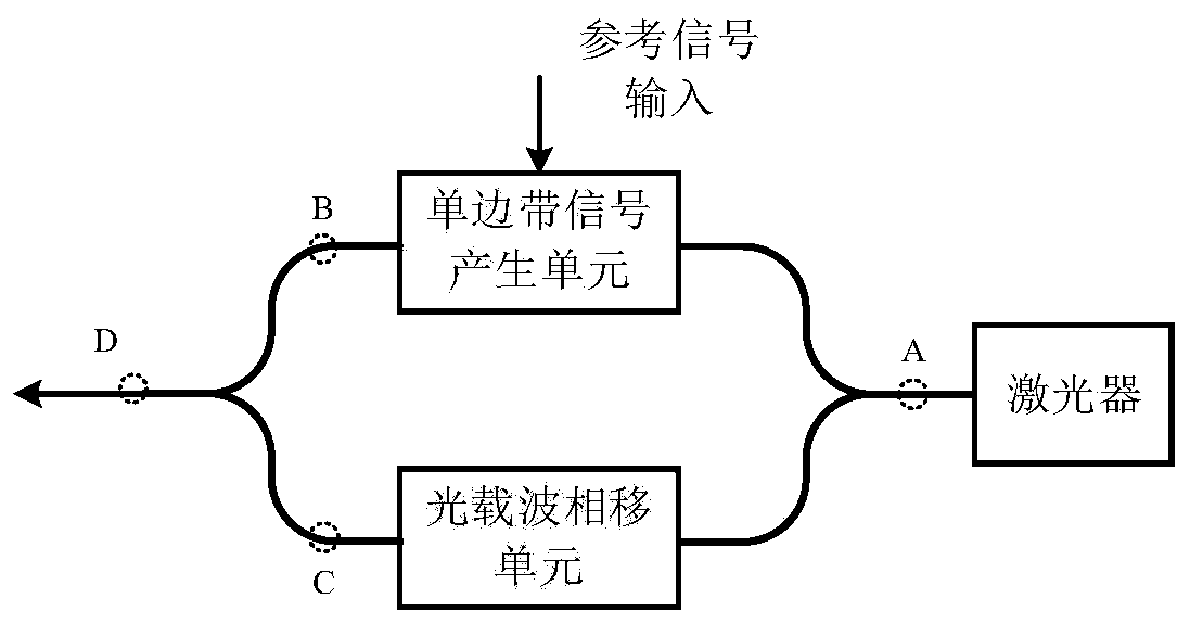
[0039] The reference signal derived from the continuous wave signal emission source is integrated with electro-optical modulation and optical domain microwave phase shift function. The integrated unit of electro-optical modulation and optical domain microwave phase shifting functions such as figure 2 As shown, it includes a laser, a single sideband signal gener...


PUM


Abstract

The invention provides a photoelectric fusion continuous wave radar leakage interference elimination device and method, and belongs to the technical field of radars. According to the photoelectric fusion continuous wave radar leakage interference elimination device, leakage interference is eliminated by adopting a microwave photon link and cable link fusion active cancellation method. And the microwave photon link regulates and controls the phase, delay and amplitude of the reference signal led out by the continuous wave signal emission source to achieve the cancellation matching conditions ofphase inversion, delay matching and equal amplitude with the leakage interference signal. The photoelectric fusion continuous wave radar leakage interference elimination device has the advantages ofwide working frequency band range, large bandwidth and high regulation and control precision, effectively suppresses leakage interference signals, and ensures high transceiving isolation of the continuous wave radar.

Description

technical field [0001] The invention belongs to the technical field of radar, and relates to a continuous wave radar leakage interference elimination device and method for photoelectric fusion. Background technique [0002] Continuous wave radar uses single-frequency, multi-frequency or frequency-modulated continuous waves for transmission and reception. Compared with pulse radar, it has the advantages of low power consumption, low interception, low-slow and small target detection, and high-range resolution. It is used in autonomous driving, It has great application potential in areas such as aircraft landing, Doppler navigation, speed measurement, and altimetry. The continuous wave working method makes the high-power transmission signal of the radar transmitter leak to the receiver and cause serious interference, which is called leakage interference. High-power leakage interference will saturate or even burn out the amplifier of the receiver, causing the system to fail to ...

Claims


Application Information

Patent Timeline
IPC IPC(8): H04B10/69H04B10/548H04B10/54G01S7/36H04B1/525
CPCH04B10/697H04B10/548H04B10/541G01S7/36H04B1/525H04B2210/006G01S7/038G01S7/023H04B1/109H04B10/25752
Inventor 韩秀友付双林苏鑫鑫武震林谷一英赵明山
Owner DALIAN UNIV OF TECH
Why Eureka
Try Eureka