Eureka AIR delivers breakthrough ideas for toughest innovation challenges, trusted by R&D personnel around the world.

Electromagnetic resonance coupling type wireless charging efficiency optimization method suitable for unmanned aerial vehicle

A resonant coupling, wireless charging technology, applied in electric vehicle charging technology, charging stations, motor vehicles, etc., can solve the problem that the position accuracy of the drone is extremely high, it is not suitable for drones, and the charging socket is difficult to self-align. and other problems, to achieve the effect of easy promotion and use, preventing interference and good use effect

Active Publication Date: 2020-07-24
中国人民解放军火箭军工程大学
View PDF13 Cites 0 Cited by
  • Summary
  • Abstract
  • Description
  • Claims
  • Application Information

AI Technical Summary

Problems solved by technology

The traditional direct contact charging method has extremely high requirements for the position accuracy of the drone, and the charging socket is difficult to align autonomously, which is not suitable for the autonomous charging system of the drone. In recent years, wireless charging technology has developed rapidly

Method used


Image

  • Electromagnetic resonance coupling type wireless charging efficiency optimization method suitable for unmanned aerial vehicle
  • Electromagnetic resonance coupling type wireless charging efficiency optimization method suitable for unmanned aerial vehicle
  • Electromagnetic resonance coupling type wireless charging efficiency optimization method suitable for unmanned aerial vehicle

Examples


Embodiment Construction

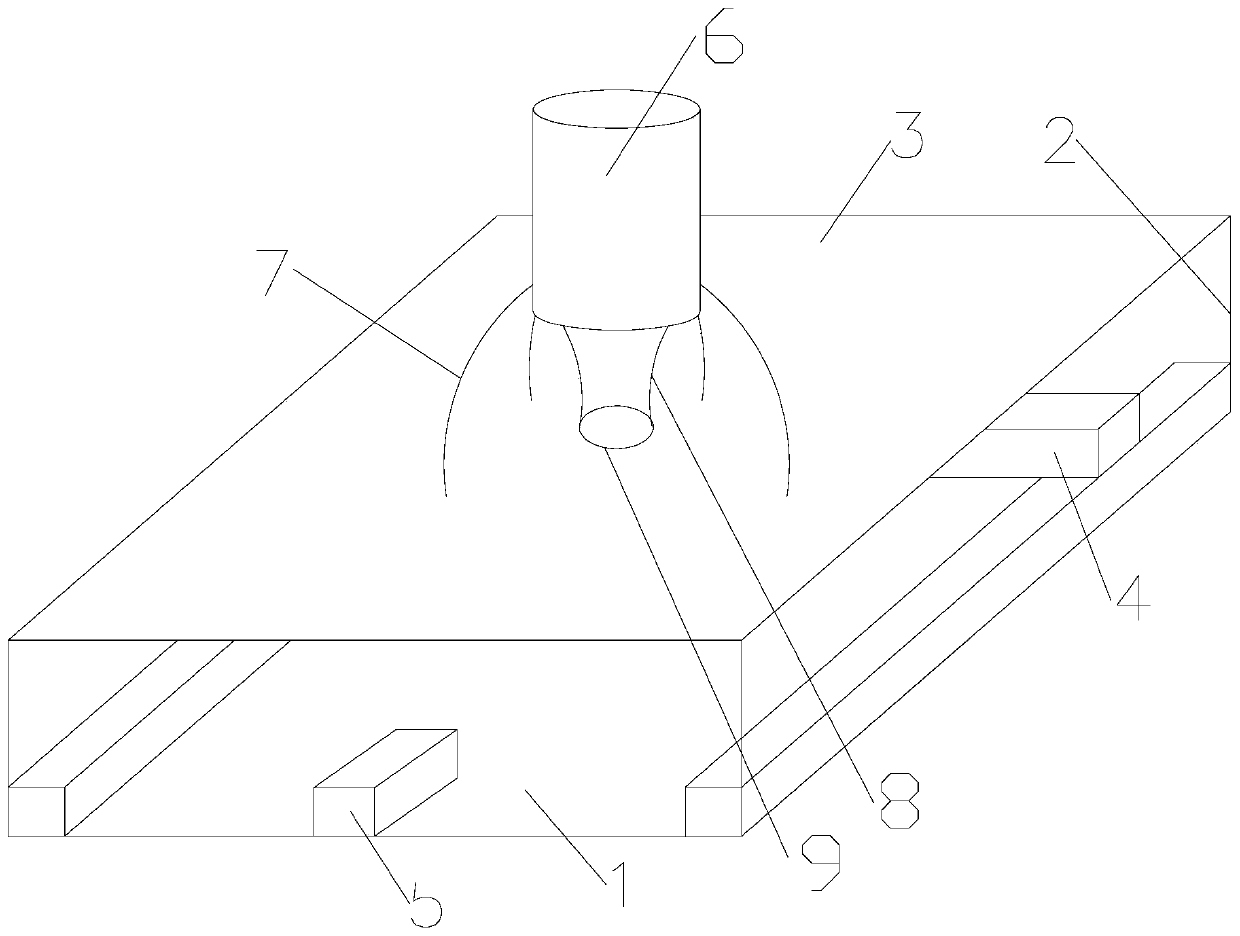
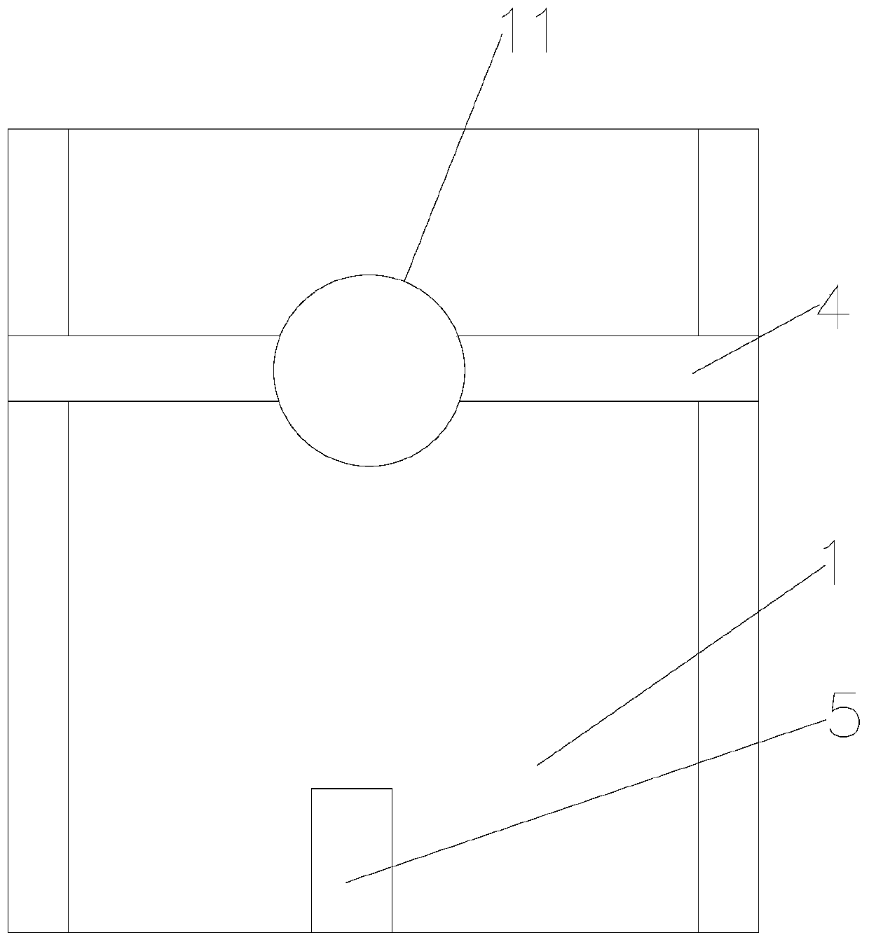
[0043] Such as Figure 1 to Figure 8 As shown, the electromagnetic resonance coupled wireless charging efficiency optimization method applicable to drones of the present invention includes the following steps:

[0044] Step 1. Design the wireless charging platform of the drone: design a wireless charging platform for charging and replenishing the drone 6. The wireless charging platform includes a wireless charging platform base plate 1 and is set on the wireless charging platform base plate 1 through a connecting column 2 The upper side and the wireless charging platform top plate 3 for the landing of the drone 6, the drone 6 is a quadrotor drone, and the four legs 7 of the quadrotor drone are located on the same ring, the The central position of the fuselage of the UAV 6 is connected with the receiving coil 9 through the receiving coil 9 mounting frame 8, and the wireless charging platform base plate 1 is provided with a wireless charging platform control box 5 and a transmit...


PUM


Abstract

The invention discloses an electromagnetic resonance coupling type wireless charging efficiency optimization method suitable for an unmanned aerial vehicle. The method comprises the following steps: 1, designing a wireless charging platform of the unmanned aerial vehicle; 2, establishing an equivalent circuit model of coil wireless charging; 3, determining the radius of a transmitting coil; 4, determining the number of turns of the transmitting coil; 5, optimizing the number of turns of a receiving coil; 6, optimizing the radius of the receiving coil; 7, optimizing the resonant frequencies ofthe transmitting coil and the receiving coil; 8, optimizing the distance between the transmitting coil and the receiving coil; and 9, performing non-coaxial optimization on the wireless power transmission efficiency of the transmitting coil and the receiving coil. The radius of the transmitting coil is determined as large as possible under the condition that the anti-interference distance is reserved, the diameter and the number of turns of the receiving coil are optimized according to the coupling relation between the transmitting coil and the receiving coil, the radius of the receiving coilis determined as small as possible under the condition that the magnetic field density is guaranteed, the resonant frequency, the distance and the non-coaxiality of the two coils are further optimized, and the wireless charging efficiency of the unmanned aerial vehicle is maximized.

Description

technical field [0001] The invention belongs to the technical field of UAV wireless charging efficiency optimization, and in particular relates to an electromagnetic resonance coupled wireless charging efficiency optimization method suitable for UAVs. Background technique [0002] In recent years, with the gradual improvement of artificial intelligence technology, intelligent hardware has begun to move towards the direction of miniaturization, low cost, and low power consumption. The continuous reduction of hardware costs has created a good development environment for the drone manufacturing industry. UAV is a powered, controllable, capable of carrying a variety of mission equipment, performing a variety of tasks and reusable aircraft, which is widely used in disaster prevention and mitigation, search and rescue, nuclear radiation detection, traffic supervision, resource exploration , Land and resources monitoring, border patrol, forest fire prevention, weather detection, cr...

Claims


Application Information

Patent Timeline
IPC IPC(8): B60L53/12B60L53/38H02J50/12
CPCB60L53/12B60L53/38H02J50/12B60L2200/10Y02T10/70Y02T10/7072Y02T90/14Y02T90/12Y02T90/16
Inventor 刘延飞王杰铃陈诚李琪王艺辉姚鹏马世欣
Owner 中国人民解放军火箭军工程大学
Why Eureka
Eureka Blog
Learn More